Introduction
Industrial facilities face mounting pressure to treat process wastewater effectively — tighter discharge regulations, water reuse goals, and rising surcharge costs from municipal treatment plants have all pushed wastewater treatment up the capital planning priority list. For facilities generating high loads of suspended solids, fats, oils, and grease (FOG), Dissolved Air Flotation (DAF) has become the default primary treatment technology.
This guide walks through the mechanical principles, key design parameters, and industry-specific applications that determine whether a DAF system performs as intended — from initial sizing through treatment train integration.
Key Takeaways
- DAF dissolves air under pressure (4–6 bar) and releases microbubbles (10–100 µm) to float suspended solids and FOG to the surface for removal
- Hydraulic surface loading rate and air-to-solids ratio are the two parameters that drive tank sizing; both require site-specific treatability testing to confirm
- Food and beverage processing, pulp and paper, oil and gas, and municipal treatment are the primary industrial users
- DAF produces thicker sludge than gravity clarifiers, has a smaller footprint, and handles low-density particles that won't settle
- Misalignment across process, plumbing, mechanical, and controls engineering is one of the most common causes of underperforming DAF systems
What Is a DAF System and How Does It Work?
Dissolved Air Flotation is a physical-chemical separation process that uses buoyancy rather than gravity to remove contaminants from water. Rather than waiting for particles to sink, DAF forces them upward by attaching microscopic air bubbles to suspended solids, FOG, and flocculated material until the combined density drops low enough for the mass to float to the surface.
The Pressurization Mechanism
The core of every DAF system is a recycle pressurization loop. A portion of clarified effluent is pumped and saturated with compressed air in a retention tank or packed column saturator, typically at 4–6 bar (approximately 58–87 psi), though some industrial configurations operate at higher pressures.
At that pressure, significantly more air dissolves into the water than at atmospheric conditions — a direct consequence of Henry's Law.
When that pressurized stream is released into the flotation tank through nozzles or pressure-reducing valves, the sudden pressure drop causes dissolved air to nucleate out of solution as microbubbles.
Typical bubble sizes fall in the 10–100 µm range, with most systems designed around a 30–50 µm average. Smaller, more uniform bubbles produce better particle adhesion and flotation.
The Process Sequence
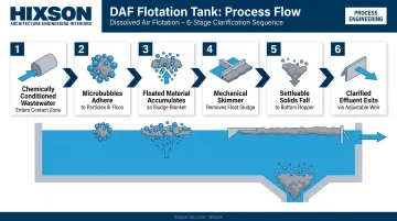
Once those microbubbles enter the flotation tank, the separation sequence moves fast:
- Chemically conditioned wastewater enters the contact zone where it meets the microbubble-laden recycle stream
- Bubbles adhere to particles and flocs, reducing their effective density until they rise
- Floated material accumulates as a sludge blanket at the water surface
- A mechanical skimmer (chain-and-flight, spiral screw, or vacuum-type) continuously removes the float sludge into a collection trough
- Settleable solids that don't float fall to a bottom hopper for separate extraction
- Clarified effluent exits via an adjustable weir at the far end of the tank
DAF typically serves as a primary (physical-chemical) treatment step, placed after screening and equalization and upstream of biological treatment. Undersized contact zones or poorly tuned recycle ratios here translate directly into excess TSS and FOG loading on downstream biological systems — raising operating costs and risking permit exceedances.
Key Design Criteria for DAF Systems
Wastewater Characterization: The Non-Negotiable Starting Point
DAF design cannot begin without a complete picture of the influent. Every sizing parameter (tank area, recycle ratio, chemical dosing) traces back to the wastewater characterization. At minimum, you need:
- Flow rates (average and peak, expressed in GPM or m³/h)
- TSS concentration and particle size distribution
- FOG concentration — free-floating or emulsified. Emulsified FOG is harder to remove and changes chemical requirements
- BOD and COD loading
- pH range and variability (critical for coagulant selection and performance)
- Temperature range (affects air solubility and system efficiency)
Bench-scale jar testing with actual wastewater samples is mandatory before finalizing any design. Parameters like the optimal air-to-solids ratio cannot be derived from textbook values alone and must be confirmed through treatability studies or documented operational experience with comparable waste streams.
Hydraulic Surface Loading Rate and Tank Sizing
Wastewater characterization data feeds directly into tank sizing. The hydraulic surface loading rate (also called surface overflow rate) is the primary sizing parameter: design flow divided by tank plan area, expressed in gpm/ft² or m/h.
| Application Type | Typical Surface Loading Rate |
|---|---|
| Standard industrial DAF | 0.2–5.5 gpm/ft² / 5–15 m/h |
| High-rate DAF (lamella/inclined plate) | 15–35 m/h |
| Desalination/SWRO pretreatment | 15–30 m/h and above |
Peak flow conditions (not average flow) must govern tank sizing. Designing to average flow leaves no capacity margin for surge events, which are common in batch-process industries.
Recycle flow adds hydraulic load to the tank and must be factored into total flow calculations. Standard industrial applications use a recycle ratio of 15–50% of influent flow. High-rate configurations may use different recycle strategies depending on tank geometry and target loading rates.
Air-to-Solids Ratio and Pressurization System Design
The air-to-solids (A/S) ratio (mass of air released per mass of solids in the influent) is the fundamental parameter controlling flotation efficiency. Published A/S values for industrial DAF applications span a wide range (0.005–0.200 lb air/lb solids), reflecting how strongly this parameter depends on the specific waste stream and particle characteristics.
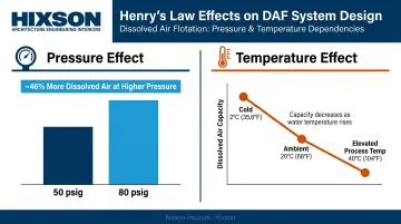
Henry's Law governs how much air can be dissolved at a given pressure and temperature. Two practical implications for design:
- Higher pressure = more dissolved air available. At 20°C, water at 80 psig can dissolve approximately 46% more air than at 50 psig
- Warmer water holds less dissolved air. Facilities with elevated process water temperatures (dairy pasteurization rinse, rendering, CIP wastewater) face reduced air saturation efficiency and need this accounted for in their recycle system design
The saturation system itself (pump, retention tank or packed column, and pressure controls) must be sized to deliver consistent recycle flow at design pressure across the expected temperature range.
Tank Configuration and Equipment Selection
Tank geometry is the first configuration decision, with three main options:
- Rectangular tanks handle larger flows, fit elongated process areas, and allow longer detention paths and are the more common choice for industrial applications
- Circular (radial-flow) tanks offer compact footprints for smaller installations
- High-rate DAF uses inclined plate (lamella) media inside the tank to multiply effective separation area within a smaller vessel footprint and is appropriate when surface loading demands exceed conventional DAF capacity or site constraints are severe
Skimmer selection affects float sludge dryness and system reliability. Chain-and-flight skimmers handle continuous high-volume applications; spiral screw designs are common in food-grade environments; vacuum skimmers can produce drier float in some configurations.
Material selection directly affects service life and capital cost. Stainless steel (304 or 316L) suits corrosive food-grade or high-FOG streams. Coated carbon steel works for less aggressive applications at lower upfront cost, though it requires closer maintenance attention over time.
Pre-Treatment and Chemical Conditioning for DAF Performance
A DAF system without proper chemical conditioning upstream is a system that will underperform. The chemistry stage is not optional — it's what makes flotation physically possible for many waste streams.
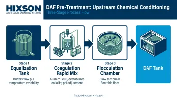
Each stage upstream of the DAF tank serves a distinct purpose:
- Coagulation: A coagulant such as alum (Al₂(SO₄)₃) or ferric chloride (FeCl₃) is added in a rapid-mix stage to destabilize colloidal particles and break emulsions. pH adjustment is typically required here, since coagulant performance is highly pH-dependent and food & beverage waste streams frequently fall outside optimal ranges.
- Flocculation: Gentle mixing follows, allowing destabilized particles to collide and build larger, floatable flocs. The chamber must be sized for both mixing energy and retention time. Undersized flocculation chambers produce weak, shear-sensitive flocs that break apart before reaching the DAF tank.
- Equalization (EQ): In batch-process facilities like food and beverage plants, an EQ tank upstream of the DAF buffers fluctuations in flow, pH, temperature, and pollutant concentration between production runs, CIP cycles, and shift changes. Without it, variable influent chemistry destabilizes the entire coagulation-flocculation system.
Chemical selection, dosing rates, and mixing design should all be validated through jar testing before full-scale implementation. Jar testing also quantifies reagent consumption, which matters: chemical costs in a mid-sized food plant DAF system can run $50,000–$150,000 per year and belong in lifecycle cost analysis from day one, not as an afterthought in capital budgeting.
DAF Applications Across Industrial Sectors
Food and Beverage Processing
DAF is the dominant primary treatment technology in food and beverage manufacturing, and the reason is physics: fats, proteins, and yeast solids have densities close to or below water. They don't settle — they float. Gravity clarifiers are largely ineffective for these streams.
The waste streams that drive DAF adoption in this sector include:
- Dairy operations — high fat and protein loads, variable pH from cleaning chemistry, emulsified FOG from milk processing
- Meat and poultry processing — high FOG, blood proteins, and suspended solids; one documented poultry rendering DAF installation achieved 99.4% TSS, 99.6% oil & grease, and 91.7% COD removal
- Breweries and beverage plants — high-BOD effluent with yeast, hop solids, and sugars; brewery wastewater BOD₅ typically ranges from 1,200–3,600 mg/L, requiring substantial FOG and solids removal before biological treatment
- Beverages and tea production — high-volume, high-BOD streams requiring pretreatment before sewer discharge or on-site biological treatment
DAF in food processing serves a dual purpose: meeting local pretreatment limits for municipal sewer discharge and conditioning the waste stream for downstream biological treatment such as MBBR or activated sludge.
Hixson has designed wastewater treatment infrastructure as part of larger facility projects across this sector — including dairy, meat and poultry, and beverage facilities — where DAF system design integrates with broader process, plumbing, and utilities engineering.
Pulp, Paper, and Packaging
In paper mills, DAF functions as both a treatment unit and a resource recovery tool. In white water circuits and deinking operations, it removes ink particles, fillers, and coatings while recovering cellulose fibers that would otherwise be lost to the drain. That dual function — treating effluent and recovering raw material — gives DAF a financial justification that goes well beyond permit compliance.
Oil, Gas, and Petrochemical
This sector generates several distinct waste streams — each containing free or emulsified oils that must be removed before discharge or reuse:
- Produced water — high-volume, oil-laden brine requiring separation ahead of disposal or injection
- Refinery cooling water blowdown — lower-volume but chronically contaminated with hydrocarbon carryover
- Tank cleaning effluent — variable, high-strength slugs with emulsified oil fractions
High-rate DAF configurations handle the large volumetric flows typical in this sector. When stable oil-in-water emulsions resist conventional coagulant treatment, electrocoagulation pretreatment is added upstream of the DAF unit.
Municipal and Desalination Applications
Municipal water resource recovery facilities use DAF for primary clarification, phosphorus removal, and sludge thickening. The EPA has documented DAF effectively thickening waste activated sludge to 3.5% total solids — significantly higher than gravity thickening typically achieves.
At desalination pretreatment plants, high-rate DAF is used to manage algal blooms and organic loading ahead of reverse osmosis membrane systems, where algae and fine particulates cause severe fouling.
Advantages and Limitations of DAF Technology
Where DAF Excels
- High removal efficiency for TSS, FOG, and BOD/COD in the right applications — performance is wastewater-dependent but well-documented across food processing and municipal sectors
- Smaller footprint than gravity sedimentation for equivalent throughput
- Shorter hydraulic retention time — manufacturer-stated holding times typically run 15–30 minutes versus several hours for gravity clarifiers
- Produces thicker float sludge than gravity sedimentation — DAF concentrations are considerably higher, which reduces downstream dewatering volume and cost
- Handles low-density particles — fats, proteins, and fine solids that won't settle no matter how long you wait
Every technology has a ceiling. These are the conditions where DAF's performance or economics work against you.
Where DAF Falls Short
- Temperature sensitivity — warmer wastewater reduces air solubility, which directly reduces bubble generation and flotation efficiency; this must be addressed in the pressurization system design
- Requires chemical pretreatment — coagulation and flocculation are mandatory upstream steps, adding ongoing operating cost and process complexity
- Energy demand — recycle pumps, pressurization equipment, and chemical feed systems carry higher energy requirements than gravity clarification
- Demands operational discipline — consistent DAF performance requires trained operators and well-calibrated automation
Neither technology is universally superior. The right choice depends on your wastewater characteristics, site constraints, and operational priorities.
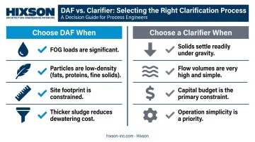
When to Choose DAF vs. a Gravity Clarifier
| Choose DAF When | Choose a Clarifier When |
|---|---|
| FOG loads are significant | Solids settle readily under gravity |
| Particles are low-density (fats, proteins, fine solids) | Flow volumes are very high and simple |
| Site footprint is constrained | Capital budget is the primary constraint |
| Thicker sludge reduces downstream dewatering cost | Operation simplicity is a priority |
Integrating DAF into Your Facility's Treatment Train
DAF never operates as a standalone unit. Its performance depends on what comes before it and what follows it — and every interface in that treatment train must be hydraulically and chemically compatible.
Upstream requirements:
- Coarse screening and grit removal to protect DAF equipment
- Equalization tank to buffer flow and chemistry variability
- Chemical conditioning system (coagulation + flocculation + pH adjustment)
Downstream integration:
- Biological treatment (MBBR, activated sludge) for BOD polishing after primary treatment
- Sludge management — thickening, filter press, or screw press — for float disposal
Controls and Automation
Consistent DAF performance in continuous operations depends on tightly managed control loops. Key control loops include:
- Automated pH monitoring and dosing control in the chemical conditioning stage
- Level control in the flotation tank and equalization basin
- Programmable sludge withdrawal timing matched to float accumulation rate
- Alarm and monitoring systems for pressure, flow, and chemistry upsets
Poorly automated DAF systems are frequently under-optimized. Operators tune chemical dosing manually, miss setpoint drift, and end up with inconsistent effluent quality. Hixson's Controls & Automation team designs integrated control systems for wastewater treatment applications — including pH monitoring, level control, and programmable withdrawal sequences — using platforms like Rockwell Automation and AVEVA.
The Multidisciplinary Design Challenge
Controls are just one piece. Integrating a DAF system into a food & beverage or industrial manufacturing facility engages multiple engineering disciplines at once:
- Process engineering — treatment system specifications, mass balances, process flow diagrams
- Plumbing systems engineering — process drainage, sanitary piping, process water connections
- Mechanical engineering — recycle pump systems, compressed air supply, heat management for process water
- Controls & automation — monitoring, dosing control, sludge withdrawal, alarm systems
- Civil engineering — site utilities, drainage, and infrastructure for the treatment area
When those disciplines operate as separate vendors coordinating through submittals and RFIs, design gaps appear at the interfaces — and those gaps typically surface during commissioning, not during design. Hixson houses all of these disciplines on a single project team, which eliminates the handoff friction that creates those gaps. Dairy operations, poultry plants, and other food & beverage facilities have engaged Hixson for DAF and broader wastewater infrastructure design specifically because of that integrated structure.
Frequently Asked Questions
What is a DAF system?
A DAF (Dissolved Air Flotation) system is a wastewater separation process that dissolves air under pressure and releases it as microbubbles inside a flotation tank. The bubbles attach to suspended solids, fats, oils, and grease, floating them to the surface for removal by skimming.
How does a DAF system work?
A DAF system works in two stages: chemical pretreatment followed by physical separation. Coagulation and flocculation first condition particles for flotation; then pressurized water saturated with dissolved air is injected through nozzles or pressure-reducing valves. The released microbubbles attach to particles and carry them to the surface, where a mechanical skimmer removes the float sludge while clarified effluent exits from below.
How do you design a DAF system?
Design starts with complete wastewater characterization (flow rates, TSS, FOG, BOD/COD, pH, and temperature), followed by bench-scale treatability testing to confirm the air-to-solids ratio. The flotation tank is then sized based on hydraulic surface loading rate, with the pressurization system, chemical conditioning equipment, and sludge handling specified to match the confirmed design parameters.
How much does a DAF system cost?
Cost varies significantly with system capacity, materials of construction, wastewater loading, and project complexity. Total project cost also includes chemical conditioning equipment, controls, installation, and connection to upstream and downstream systems. Reliable budgeting requires a site-specific engineering evaluation. Publicly available price ranges rarely account for the site variables that most affect final cost.
What industries use DAF systems?
Primary users include:
- Food and beverage processing (dairy, meat and poultry, brewing, beverages)
- Pulp and paper manufacturing
- Oil and gas operations
- Municipal wastewater treatment
- Desalination and water reuse facilities
Any industry generating wastewater with high suspended solids, significant FOG loading, or fine low-density particles that won't settle under gravity is a strong candidate.
What is the difference between a DAF system and a clarifier?
Clarifiers use gravity to settle solids to the tank bottom; DAF uses buoyancy from microbubbles to float solids to the surface. DAF handles low-density particles like fats and proteins that gravity can't effectively settle, produces thicker sludge, and fits in a smaller footprint. Gravity clarifiers are simpler and lower-cost for streams where solids settle readily without chemical assistance.