
Introduction
A two-inch chilled water pipe can deliver as much cooling capacity as a 42-inch air duct. That single comparison explains why hospitals, food and beverage plants, pharmaceutical facilities, and science and technology buildings rely on chilled water systems when standalone HVAC units can't meet centralized, scalable demands.
The engineering complexity is real. A poorly designed or operated CHW system wastes energy, creates hot spots, and leads to costly downtime. A well-designed one delivers precise, reliable cooling for decades.
This guide covers how CHW systems work, their key components, design fundamentals, pumping strategies, efficiency optimization, and maintenance. It also addresses specialized industrial applications where hygienic design, cGMP compliance, and process cooling requirements shape every decision.
Summary
- A chilled water system circulates cooled water (typically 44°F supply) through a closed loop to absorb heat from a building or process, then returns warmer water (typically 54–56°F) to the chiller for re-cooling
- The four core components are the chiller, pumps, cooling tower (in water-cooled systems), and air handling or fan coil units
- System design hinges on accurate load calculation, delta T selection, and pumping scheme — primary-secondary or variable primary
- Variable frequency drives, chiller sequencing, and BAS integration deliver the greatest energy efficiency gains
- Water treatment and air removal are the most overlooked maintenance priorities — and the most likely to cause failures if neglected
What Is a Chilled Water System and How Does It Work?
A chilled water (CHW) system is a centralized mechanical cooling solution that uses water as the heat transfer medium, circulating it between a chiller plant and terminal cooling units across a building or campus. The core advantages are efficiency and precision: chilled water distribution requires far less space than air-based systems and delivers accurate temperature control — particularly valuable for variable air volume (VAV) applications.
The Refrigeration Cycle
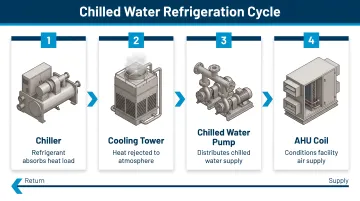
The chiller itself operates in four stages: the compressor pressurizes refrigerant vapor, the condenser rejects heat to either outdoor air or condenser water, an expansion valve reduces refrigerant pressure, and the evaporator absorbs heat from the chilled water loop. This process produces cold water without direct contact between refrigerant and building air, enabling centralized cooling with distributed delivery.
Two Primary Water Loops
System architecture is defined by two primary water loops:
- Chilled water loop: Moves cold water from the chiller evaporator to AHUs or fan coils where building heat is absorbed, then returns warmer water to the chiller
- Condenser water loop: In water-cooled systems, moves heat from the chiller condenser to the cooling tower for rejection to the atmosphere
Closed-Loop vs. Open-Loop Configurations
Loop configuration determines water quality management approach. Closed loops recirculate the same treated water in a sealed path (most common for CHW distribution), minimizing contamination and simplifying water treatment. Open systems like cooling towers introduce atmospheric exposure and evaporation, requiring more rigorous treatment programs to control scaling, corrosion, and biological growth.
Loop type feeds directly into application requirements. CHW systems serve two distinct use cases: comfort cooling (HVAC for occupied spaces) and process cooling (temperature control for manufacturing, food processing, laboratory equipment, and pharmaceutical production). The distinction affects design parameters considerably — process cooling demands tighter temperature tolerances, higher reliability, redundancy, and hygienic design principles in food and pharmaceutical applications.
According to LBNL research, central chillers serve 45% of all federal building floor area (approximately 640 million square feet) and 61% of large federal buildings—demonstrating the dominant role of chilled water systems in large-scale facilities.
The Four Key Components of a Chilled Water System
Chillers
The chiller is the heart of the system—a refrigeration machine that extracts heat from chilled water by running it across an evaporator heat exchanger. Two primary types differ in how they reject that heat.
| Water-Cooled | Air-Cooled | |
|---|---|---|
| Heat rejection | Condenser water loop + cooling tower | Refrigerant-to-air condensers |
| Full-load efficiency | ~0.55 kW/ton (0.64 kW/ton system) | ~10.9 EER |
| Footprint/complexity | Larger; more ancillary equipment | Compact; simpler installation |
| Best fit | High-efficiency applications, larger plants | Sites without cooling tower access |
Part-load performance matters more than full-load ratings. Buildings operate at design load less than 2% of the time, making Integrated Part Load Value (IPLV) the primary selection metric. Best-available NPLV reaches 0.35 kW/ton; VFD-equipped chillers typically achieve around 0.386 kW/ton—compared to older units running at 1 kW/ton or more. Chiller selection is governed by AHRI Standard 550/590, which covers water-cooled, air-cooled, and evaporatively-cooled configurations.
Pumps
Pumps serve two distinct roles in a CHW system:
- Chilled water pumps (primary and/or secondary) circulate water through the building loop to terminal units
- Condenser water pumps move water between the chiller condenser and cooling tower in water-cooled systems
Pump sizing directly affects pressure drop, pipe velocities, and energy consumption. Oversizing wastes energy and creates unnecessary pressure drop; undersizing leads to inadequate flow and reduced cooling capacity.
Cooling Towers
Cooling towers reject heat from the condenser water loop through evaporative cooling. Warm condenser water trickles over fill media while fans draw air through, causing a portion of the water to evaporate and carry heat away.
Approach temperature—the difference between leaving water temperature and entering air wet-bulb temperature—typically ranges from 4 to 5°F. Cooling tower performance directly governs chiller efficiency: each 1°F reduction in condenser water temperature improves chiller efficiency by 1.0–2.6% depending on compressor type, with VFD centrifugal chillers showing the greatest sensitivity at 2.4–2.6% improvement per degree.
Air Handling Units (AHUs) and Fan Coil Units (FCUs)
AHUs and FCUs are where actual space or process cooling occurs—warm building air passes over chilled water coils, transferring heat to the water. The distinction comes down to scale and distribution:
- Central AHUs serve large zones via ductwork, offering centralized filtration and air treatment
- Distributed FCUs serve individual rooms or zones with simpler installation and localized control
Both affect return water temperature and overall loop delta T. Poorly performing coils, oversized valves, or low airflow can trigger low delta T syndrome—one of the most common and costly operational failures in CHW systems.
Ancillary Components
Supporting components critical to safe and stable operation include:
- Expansion tanks: Accommodate water volume changes with temperature fluctuation
- Air separators/eliminators: Remove dissolved and entrained air before it causes corrosion or flow problems
- Control valves: Two-way or three-way valves modulate flow to terminal units
- Instrumentation: Temperature sensors, flow meters, and pressure gauges feed the control system and enable performance monitoring
Chilled Water System Design: Engineering Fundamentals
Successful CHW system design begins with accurate building load calculation—typically expressed in tons of refrigeration or BTU/hr. Load calculations account for envelope heat gain, occupancy, internal equipment, ventilation, and any process heat loads. Oversizing or undersizing chillers creates efficiency and reliability problems that compound over the system's lifespan. Oversized equipment operates inefficiently at partial loads, while undersized equipment can't meet peak demands.
Temperature delta (ΔT) selection affects every component in the system. Standard design conditions are 44°F chilled water supply temperature and 54°F return (10°F delta T) at a flow rate of 2.4 gpm/ton.
A larger ΔT (14–16°F) reduces flow rates, lowers pump energy, and allows smaller pipe sizes—but requires more careful coil and control valve design to ensure proper heat transfer. Large plants often use 18°F or greater ranges to minimize pumping and piping costs, sometimes with supply temperatures as low as 40–42°F to maintain adequate coil performance.
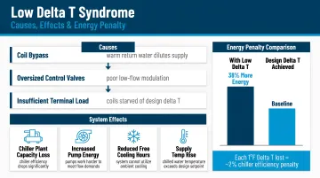
Low delta T syndrome occurs when actual return water temperatures fall below design values, cutting the system's effective capacity and forcing operators to run extra chillers and pumps. Common root causes include:
- Oversized coils or three-way control valves
- Poor coil performance from fouling or inadequate maintenance
- Excess flow from improperly balanced circuits
Research documents a 27% increase in chiller auxiliary energy when delta T degrades, making it one of the most persistent and costly CHW system problems in practice.
Hydraulic modeling is a non-negotiable design step. Pressure drop calculations for every component and pipe segment determine pump head requirements, dictate pipe pressure class ratings, and identify the index circuit (the most pressure-challenged path). In variable flow systems, engineers must also model minimum chiller flow requirements to prevent evaporator damage from low velocities.
Codes and standards that govern CHW system design include:
- ASHRAE Standard 90.1-2022: Minimum energy efficiency requirements for chillers, pumping, and controls
- ASHRAE Standard 15-2024: Refrigerant safety and machinery room requirements
- ASHRAE Guideline 22-2025: Instrumentation for monitoring CHW plant efficiency
On complex multi-discipline projects—particularly in food and beverage, pharmaceutical, and science and technology facilities—an integrated MEP engineering approach where mechanical, electrical, structural, and controls disciplines work from a shared design model helps catch code conflicts early and prevents costly field changes.
Pumping Schemes: Primary-Secondary vs. Variable Primary
The pumping scheme you choose shapes both operating efficiency and long-term energy costs — and the two dominant approaches each make a different trade-off.
Primary-Secondary (PS) Pumping
A constant-volume primary loop maintains minimum required flow through each chiller, while a variable-volume secondary loop responds to actual building demand. A decoupler or bypass pipe separates the two loops and prevents chiller flow starvation.
Primary-secondary systems offer real operational advantages:
- Simpler controls with less commissioning complexity
- Inherent protection against low chiller flow
- More forgiving for operators with less system familiarity
The trade-off is pumping efficiency. The constant primary loop runs regardless of actual building demand, which creates energy waste during part-load conditions.
Variable Primary (VP) Pumping
A single variable-flow loop uses VFDs to modulate pump speed based on differential pressure and demand, flowing directly through the chillers at variable rates.
The central challenge is maintaining manufacturer-required minimum chiller flow rates at low-load conditions. Control systems manage this through chiller sequencing and bypass valves — which means more sophisticated programming and commissioning upfront.
The energy payoff, though, is measurable. Research shows variable primary flow reduces pump energy 25–50% compared to primary-secondary systems, cuts total annual plant energy by 3–8%, and lowers both first costs (4–8%) and life cycle costs (3–5%).
Decision Framework
| Factor | Primary-Secondary | Variable Primary |
|---|---|---|
| Controls complexity | Lower | Higher |
| Operator familiarity required | Less | More |
| First cost | Higher | 4–8% lower |
| Life cycle cost | Higher | 3–5% lower |
| Best fit | Retrofit, redundancy-critical systems | New high-efficiency designs |
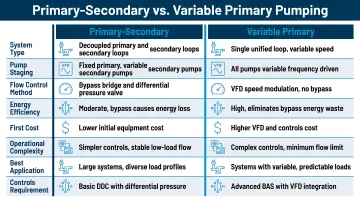
Variable primary is increasingly the default for new builds where energy performance is a priority. Primary-secondary remains the right call when operational simplicity or existing operator expertise drives the decision.
Energy Efficiency Strategies and System Controls
Variable Frequency Drives (VFDs)
VFD application on chilled water pumps, condenser water pumps, and cooling tower fans typically delivers the greatest energy savings among common control strategies. Since pump power scales with the cube of flow rate, even modest speed reductions yield significant savings.
Under the affinity laws, a 20% reduction in pump speed cuts input power by approximately 50%. A 50% flow reduction can reduce pumping power by as much as 80%.
Installing variable-speed drives on cooling delivery systems can reduce energy use by 30–50% in typical applications.
Chiller Sequencing and Staging Logic
In multi-chiller plants, the goal is to load each operating chiller within its most efficient range—typically 60–85% of full load—rather than running all units at low partial loads.
Building automation system (BAS)-driven sequencing can use kW/ton metrics, differential pressure, or BTU metering to trigger chiller starts and stops automatically, ensuring optimal plant efficiency across all load conditions.
CHW Supply Temperature Reset
Raising CHW supply temperature setpoint during low-load or low-humidity conditions reduces compressor energy. Research shows that raising chilled water temperature by 1°F reduces chiller energy by approximately 2%, with VFD chillers achieving 2–3% savings per degree.
Annual savings from reset strategies typically range from 5–10% compared to fixed setpoint operation.
Waterside Economizers
Where compressor-side strategies hit their limits, waterside economizers offer a different lever. They provide "free cooling" by routing condenser water directly (or through a heat exchanger) to the chilled water loop when outdoor wet-bulb temperatures are low enough to displace mechanical cooling.
Effectiveness, however, varies considerably by climate and building type:
- Cooling load offset ranges from 0.4–27.4% of annual ton-hours depending on location and application
- Hospitals in cooler climates capture the highest offset percentages
- High-efficiency variable-speed chiller plants operating at 0.36 kW/ton set a threshold economizers must beat to justify their capital cost and added complexity
Maintenance, Water Quality, and Common Issues
Water Treatment
Water treatment is the most critical ongoing maintenance task. Without a comprehensive program managing pH, alkalinity, hardness, dissolved solids, corrosion inhibitors, and biocides, CHW systems accumulate scale on heat transfer surfaces and develop corrosion and biological growth.
Scale impact on efficiency is dramatic. Just 0.024 inches of calcium carbonate scale reduces heat transfer by approximately 34%, requiring a 170% increase in heat transfer area to compensate. Dirty evaporator and condenser tubes can increase compressor energy consumption by 30% or more.
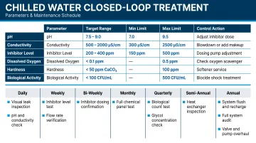
Recommended closed-loop water treatment parameters include:
- pH range: 8.0–9.5 (alkaline range prevents iron and copper corrosion)
- Corrosion inhibitors: nitrites for steel protection, azoles for copper protection
- Oxygen scavengers: sulfite-based compounds to remove dissolved oxygen
- Regular monitoring: conductivity as a key performance indicator
Air Removal
Dissolved and entrained air in closed loops causes oxygen-driven corrosion, noisy piping, reduced flow, and poor heat transfer. Proper placement of air separators, correct pressurization of the expansion tank, and periodic manual bleeding of high points are standard practices.
Because air introduction accelerates oxygen-driven corrosion, tracking actual metal loss matters. Corrosion coupons — sacrificial metal strips placed in the system — provide a direct measure of corrosion rates over 90-day intervals.
Preventive Maintenance Framework
A comprehensive preventive maintenance program covers major failure points:
- Inspect pump bearings, mechanical seals, and impellers on a scheduled basis
- Clean evaporator and condenser tubes periodically to maintain heat transfer efficiency
- Calibrate temperature sensors, pressure transducers, and flow meters to keep readings reliable
- Review BAS alarm logs regularly to catch developing issues before failure occurs
Frequently Asked Questions
How does a chilled water system work?
A chiller cools water to approximately 44°F, which is then pumped through pipes to air handling units or fan coils where building heat is absorbed. The warmed water returns to the chiller, and in water-cooled systems, that heat is rejected to the atmosphere via a cooling tower.
What are the four major components of a chilled water system?
The chiller produces chilled water, pumps circulate water through the system, the cooling tower rejects heat in water-cooled systems, and air handling units or fan coil units deliver cooling to conditioned spaces or processes.
Which is better, VRF or chiller?
VRF systems are better suited for smaller, multi-zone buildings where individual zone control and lower upfront cost are priorities. Chilled water systems are preferred for large or complex facilities due to superior scalability, energy efficiency at high loads, and suitability for process cooling applications.
What does a chiller engineer do?
A chiller engineer designs, specifies, commissions, and optimizes chilled water plant equipment and systems. This covers load calculations, equipment selection, pumping scheme design, controls integration, and ongoing performance analysis to ensure the system meets efficiency and reliability targets.
What is low delta T syndrome and why does it matter?
Low delta T syndrome occurs when chilled water returns to the chiller at a lower temperature than designed, reducing effective plant capacity and forcing operators to run additional chillers and pumps unnecessarily. This wastes energy and can prevent the system from meeting full cooling demand.
What is the difference between primary-secondary and variable primary pumping?
Primary-secondary systems use separate constant-flow and variable-flow pump loops decoupled by a bypass pipe. Variable primary systems replace both loops with a single variable-flow loop, using VFDs to modulate flow directly through the chillers. Variable primary offers greater energy efficiency but requires more sophisticated controls.