Introduction
CIP system design and installation is a technically demanding undertaking that extends far beyond equipment procurement. Effective CIP requires tight coordination across facility architecture, process engineering, piping design, and controls/automation—and the consequences of design-stage errors are significant. An analysis of 1,576 FDA food recalls in 2025 found that 73.7% of all Class I recalls (the most serious category) stemmed from microbial contamination, yet this category receives less regulatory technology investment than most other compliance areas.
The 2024 Boar's Head Listeria outbreak demonstrates what happens when sanitation systems fail. USDA FSIS investigators attributed 10 deaths across 19+ states to "inadequate sanitation practices," including meat and fat residue on equipment from previous production days, condensation dripping onto exposed food products, and structural cracks collecting moisture near machinery. Investigators found these violations were not isolated incidents — they reflected a routine pattern of systemic failure across the operation.
Getting CIP right starts at the design stage — not during commissioning or after a failed audit. Poorly designed or installed systems produce predictable failure modes:
- Dead-leg contamination zones where cleaning solution never reaches
- Inadequate flow velocity that causes validation failures
- Non-drainable process lines that harbor residual product
- Systems that cannot meet FDA/HACCP documentation requirements
Industry estimates put the cost of retrofitting CIP deficiencies at 3–10x the cost of designing them correctly from the start. This guide covers the design decisions and installation steps that prevent those outcomes.
Summary
Key takeaways for effective CIP system design and installation:
- Integrate CIP at the facility concept stage; retrofitting an existing facility nearly always compromises performance and inflates costs
- Equipment compatibility is non-negotiable: tanks need spray coverage, pumps must drain properly, all lines self-draining with zero dead legs
- Match system type — single-use or recirculating, single-loop or multi-loop — to your facility's scale and cleaning frequency
- Installation follows a strict sequence: site prep → skid placement → piping → controls → integration → validation
- HACCP compliance requires documented validation before production begins—this is regulatory, not optional
Key Design Factors Before CIP Installation Begins
Design decisions made during the facility concept phase determine whether CIP installation proceeds smoothly or requires expensive rework. These prerequisites must be resolved before any equipment is procured or piping laid.
Equipment and Process Line Compatibility
Tank Design: All tanks in the system must be designed with spray ball or rotating spray device ports positioned to achieve full internal coverage. Internal geometry must eliminate shadow zones—areas where cleaning solution cannot reach directly. Older tanks may require port additions, interior modifications, or complete replacement to meet 3-A Sanitary Standard 78-03 for spray cleaning devices.
Pump Configuration: Positive displacement and process pumps must be CIP-compatible:
- Drain port orientation (typically vertical) to ensure complete drainage
- Seal materials rated for repeated chemical exposure (caustic at 65-80°C, acid at up to 50°C)
- Valve control allowing CIP solution to flow through or bypass the pump without leaving stagnant zones
Dead-Leg Elimination: Dead legs—pipe branches where cleaning solution does not flow adequately—create zones where product residue, moisture, and bacteria accumulate. Two standards govern dead-leg design:
| Standard | Maximum Length | Measurement Point | Application |
|---|---|---|---|
| 3-A Sanitary Standards | 2× pipe diameter | From pipe wall | General food processing equipment |
| EHEDG (EN1672-2:2020) | 1× pipe diameter | From pipe wall | CIP-cleaned food systems |
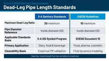
For high-risk products or complex rheology (high viscosity), apply the stricter 1D rule or eliminate dead legs entirely. Every pipe branch, valve body, and instrument connection must be assessed during design. Dead legs beyond these limits must be rerouted, eliminated, or equipped with dedicated flush points.
Drainage, Slope, and Facility Infrastructure
Pipe Slope Requirements: All process lines and vessel connections must drain completely between CIP cycles. Standing water enables bacterial growth. USDA Guidelines specify that piping must be installed with "sufficient slope for drainage," 1% minimum (1 cm drop per meter of horizontal run). Drain points must be installed at all low spots in the system.
Utility Infrastructure: Confirm these utilities are in place or planned before installation begins:
- Steam or hot water supply: Chemical heating (caustic typically requires 65-80°C)
- Water supply: Adequate pressure and volume for target flow velocities (1.5-2.1 m/s)
- Electrical service: CIP skid pump motors, controls, instrumentation
- Chemical storage area: Secondary containment for caustic, acid, and sanitizer tanks
- Floor drainage: Beneath CIP skid and at all process equipment drain points
CIP System Type Selection
Type I (Single-Use) vs. Type II (Recirculating):
Type I systems prepare fresh chemical solution for each cycle and discard it after use. Lower capital cost and simpler operation make them attractive for smaller facilities, but chemical and water consumption per cycle is higher.
Type II systems recirculate solutions across multiple cleaning cycles, cutting chemical consumption by 50-70% in high-frequency operations. The tradeoff is larger multi-tank configurations, heat exchangers, additional pumps, and greater upfront investment.
The right choice depends on:
- CIP frequency (how many cycles per week)
- Facility scale (number of circuits and total volume)
- Chemical cost targets (calculate total cost of ownership over 5-10 years)
- Water/wastewater constraints (some regions penalize high water usage)
Single-Loop vs. Multi-Loop Design:
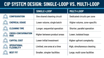
Single-loop systems clean one circuit at a time. They're appropriate for smaller facilities with limited production lines and longer cleaning windows.
Multi-loop systems share a central chemical and water supply across multiple circuits, enabling simultaneous cleaning of different equipment. For facilities running multiple production lines, dual-circuit configurations can cut total cleaning time by 50% compared to single-circuit setups—a meaningful operational difference at high changeover frequency.
Regulatory and Zone-Based Design Requirements
FDA CGMP Requirements: 21 CFR 117.40(d) mandates that closed and automated systems "be of a design and construction that enables them to be maintained in an appropriate clean and sanitary condition." CIP capability is not optional—it's a regulatory requirement for equipment that cannot be manually disassembled and cleaned.
Raw vs. Ready-to-Eat (RTE) Separation: USDA FSIS mandates physical separation of RTE and raw processing areas, including:
- Non-cross-connected floor drains
- Separate traffic patterns for personnel and equipment
- Positive air pressure from RTE rooms into raw areas
Cross-contamination risk between raw and RTE zones makes shared CIP systems problematic. New facility designs should incorporate dedicated CIP circuits for each zone from the outset. Shared systems require more frequent chemical recharging and introduce cross-contamination risks that are difficult to fully mitigate.
Integrated Design Team Advantage: CIP incompatibilities discovered after installation begins are expensive to fix. Coordinating process design, facility layout, and controls engineering under one roof—before procurement starts—is the most effective way to avoid that outcome. Hixson's Food & Beverage team does exactly that: 20 in-house technical disciplines and a Controls & Automation group with 75+ years of combined experience work through these interdependencies during design, not during construction.
How to Install a CIP System in a Food Processing Facility
CIP installation follows a defined sequence. Deviating from this order—especially by rushing to connect chemical supply before piping and controls are fully verified—is a leading cause of rework and validation failures.
Site Preparation and Utility Connections
Finalize CIP Skid Location:
- Adequate clearance for maintenance access (minimum 3 feet on all sides)
- Proper floor drainage beneath the skid
- Proximity to circuits being served (long supply and return runs increase pressure drop and may require pump oversizing)
Verify Utility Connections: Before skid placement, confirm these connections are complete and tested to required specifications:
- Hot water or steam supply (temperature, pressure, flow rate)
- Chilled or ambient water supply (volume, pressure)
- Electrical service (voltage, amperage, grounding)
- Drain lines (capacity, slope, tie-in points)
CIP Skid Placement and Piping Installation
Skid Positioning: Position and anchor the CIP skid according to supplier and engineering drawings. Confirm:
- All tanks, pumps, and heat exchangers are properly supported
- Skid connections align with facility supply and return headers
- No forced-fit connections that introduce stress on fittings
With the skid anchored and connections confirmed, begin piping installation.
Sanitary Piping Installation: Install all process and CIP supply/return piping using sanitary fittings (tri-clamp or equivalent per 3-A Sanitary Standards 63-04):
- Maintain specified drainage slopes throughout (minimum 1% slope)
- Verify all welds are sanitary-finished (smooth, flush, Ra ≤ 32 microinches) with butt weld offset no more than ±1/32 inch
- Inspect welds before insulation or enclosure is applied (borescope inspection recommended)
- Use eccentric reducers (not concentric) to prevent air pockets and drainage issues
Mix-Proof Valves: Install mix-proof valves at circuit junctions where simultaneous cleaning of one circuit while producing on another is required. These double-block-and-bleed valves direct pressurized cleaning fluids without cross-contamination risk.
They add upfront cost but significantly improve operational flexibility and reduce cleaning downtime, especially in dairy plants or facilities with frequent product changeovers.
Controls, Instrumentation, and System Integration
Instrumentation Installation: Install sensors at CIP return points and within the skid:
- Temperature sensors: Confirm chemical heating targets are reached (typically 65-80°C for caustic)
- Conductivity sensors: Verify chemical concentration and enable dosing control; detect phase transitions between rinse and chemical steps
- Flow meters: Confirm adequate velocity (1.5-2.1 m/s minimum) is achieved throughout each circuit
PLC/SCADA Integration: Integrate the CIP control system with the facility's process control architecture:
- Enable automated cycle selection based on which product was run
- Generate automated recordkeeping of cycle parameters (time, temperature, conductivity, flow rate)
- Trigger alarm notification for any parameter falling outside the validated range
- Ensure tamper-evident compliance records aligned with 21 CFR Part 117 and FSMA Preventive Controls
Once controls are integrated and validated ranges confirmed, recipe programming translates that framework into executable cleaning sequences.
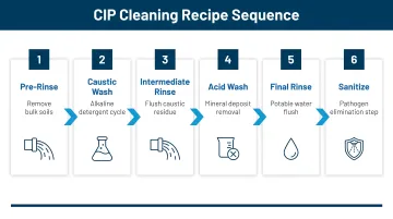
CIP Recipe Programming: Program CIP recipes in consultation with the chemical supplier and validate them against the specific soil types, product residues, and allergen requirements of the facility's production matrix. Standard recipes follow this sequence:
- Pre-rinse with water (removes bulk soil before chemistry is introduced)
- Caustic wash (2-4% NaOH at 65-80°C)
- Intermediate rinse (flushes caustic residue before acid contact)
- Acid wash (0.5% nitric acid at up to 50°C)
- Final rinse
- Sanitize (optional: 100 ppm hypochlorite at 25°C for 2 minutes)
Post-Installation Checks and Validation
Validation is not optional. It is how a facility confirms the installed CIP system achieves the intended level of sanitation — and it is a required element of both HACCP-based food safety plans and FDA CGMP compliance.
Visual and Structural Verification
Conduct a full walkthrough of all installed piping, valves, and connections before first wet commissioning:
- Verify drainage slopes with a level
- Confirm no dead-leg configurations exist beyond standard limits (2D for 3-A; 1D for EHEDG)
- Check that all sanitary fittings are correctly seated and clamps are torqued
- Confirm spray devices are correctly positioned within vessels for full internal coverage
Functional and Performance Testing
Water-Only Commissioning
Run water-only cycles through each CIP circuit to confirm:
- Adequate flow velocity per equipment supplier and process design specifications (minimum 1.5 m/s; Reynolds number >4,000 for turbulent flow)
- Correct return routing with no leaks or cross-connections
- All automated valves cycle in the correct sequence without manual intervention
With mechanical performance confirmed, move to chemical cycle testing. Monitor and record conductivity, temperature, and flow at the CIP return during initial chemical cycles:
- Setpoints are reached and maintained consistently
- Dosing control is stable without conductivity overshoot (indicating inline dosing lag)
- Chemical concentrations match recipe specifications
Cleaning Validation and Documentation
Successful functional testing confirms the system operates as designed. Cleaning validation confirms it actually cleans — verifying that each CIP recipe removes the specific soils and residues present in your process.
Validate each CIP recipe against the product and soil types it will clean:
- Swab testing: Sample food-contact surfaces after CIP cycles
- Rinse water sampling: Test return water for residues
- ATP bioluminescence: Rapid validation tool for confirming surface cleanliness and allergen residue reduction
- Allergen testing: Verify allergen levels drop to non-detectable
Document all validation results as CIP validation records supporting the facility's HACCP plan. These records must be available for regulatory audit.
Common CIP Installation Problems and Fixes
These are the most common problems encountered during CIP commissioning — and in nearly every case, they trace back to a design or installation decision made earlier in the project.
Dead-Leg Contamination Zones
Swab testing or rinse water sampling fails in specific equipment areas after CIP cycles — a reliable indicator of incomplete cleaning in localized zones. The usual culprit is pipe branches, valve bodies, or instrument connections that extend beyond the recommended dead-leg length ratio (2D per 3-A; 1D per EHEDG) and receive inadequate flow during the cycle.
Fixes:
- Reroute or eliminate dead-leg branches
- Install dedicated flush points at confirmed dead-leg locations
- In valve clusters, confirm all valve bodies are included in the CIP circuit flow path
Inadequate Flow Velocity Leading to Failed Cleaning
CIP cycles complete without error flags, yet physical residue or failed swab tests confirm surfaces aren't being cleaned. Two root causes are common here: the supply pump is undersized for the total circuit length and fittings, or the circuit includes diameter changes that drop velocity in larger-bore sections below the minimum turbulent flow threshold (Reynolds number <4,000).
Fixes:
- Review hydraulic calculations for each circuit
- Resize supply pump if pressure drop analysis confirms undersizing
- Redesign oversized pipe segments or add flow restrictors to maintain minimum velocity (1.5 m/s)

Chemical Concentration Inconsistency
Erratic or out-of-range conductivity readings at the CIP return point to concentration problems — either under-cleaning or excessive chemical use. Two distinct causes should be evaluated: inline dosing with insufficient lag compensation, which produces conductivity overshoot and over-dosing; and chemical storage tank volume too small for the circuit, which causes dilution as the cycle runs.
Fixes:
- Adjust dosing control logic to account for sensor lag delay
- Switch to pre-mix dosing in solution tank rather than inline dosing for more stable concentration control
- Verify chemical tank sizing is adequate for the largest circuit volume plus system hold volume
Pro Tips for Effective CIP System Design and Installation
Design CIP into the facility from the earliest project phase. CIP-compatible equipment selection, drainage slope requirements, utility routing, and skid placement all affect facility layout decisions that are costly to reverse after construction begins.
Specify mix-proof valves at circuit junctions during the design phase. The upfront cost premium is typically recovered quickly through the operational efficiency of cleaning one production circuit while another continues to produce—particularly valuable in multi-product or high-changeover facilities.
Establish full CIP documentation as a project deliverable. Validated CIP recipes, as-built piping drawings, instrument calibration records, and validation test results should all be organized and audit-ready before the facility begins production.
Partner with an integrated architecture and engineering firm. For complex multi-line facilities or greenfield food processing plants, working with a full-service firm that integrates process design, facility layout, and controls under one roof reduces coordination gaps and keeps CIP decisions embedded in the project from day one. Hixson's Controls & Automation group, for example, works alongside process and architectural teams from inception through startup—so CIP design is built in, not bolted on at the end.
Frequently Asked Questions
What is CIP in the food industry?
CIP (Clean-In-Place) is an automated method of cleaning the interior surfaces of processing equipment—tanks, pipes, vessels, and filling lines—without disassembly. It uses circulated water, cleaning chemicals, and heat to achieve sanitation. CIP is a regulatory and food safety requirement across most food and beverage manufacturing operations.
What are the 5 steps of CIP?
A standard CIP sequence follows five steps:
- Pre-rinse with water
- Caustic wash to remove organics
- Intermediate rinse
- Acid wash to remove mineral scale
- Final rinse
A sanitizer step is added as a sixth step in higher-risk applications, including dairy and pharmaceutical facilities.
Does CIP need to be validated in HACCP?
Yes, CIP must be validated as part of a HACCP-based food safety plan. Validation demonstrates that the cleaning process consistently achieves the required level of sanitation for each product type. Validation records must be maintained and available for regulatory inspection.
What is the difference between a single-use and a reuse CIP system?
A Type I (single-use) system prepares fresh chemical solution for each cycle and discards it after use. A Type II (reuse/recirculating) system stores and recirculates solution across multiple cycles, reducing chemical costs but requiring higher upfront capital investment in additional tanks and controls.
What are dead legs in a CIP system and why do they matter?
Dead legs are sections of pipe or valve bodies where cleaning solution does not flow adequately during a CIP cycle, creating zones where product residue, moisture, and bacteria can accumulate. Eliminating dead legs is a fundamental requirement of sanitary piping design and 3-A Sanitary Standards compliance.
Should raw and ready-to-eat areas have separate CIP systems?
The FDA recommends separate CIP systems for raw and RTE (ready-to-eat) areas to prevent cross-contamination. New facility designs should incorporate this separation from the outset. Shared systems require more frequent chemical recharging and introduce cross-contamination risks that are hard to eliminate entirely.