Introduction
Pharmaceutical plant layout design operates in a fundamentally different world than conventional industrial facilities. Every spatial decision directly impacts product safety, regulatory approval, and patient outcomes. A poorly conceived layout can trigger FDA warning letters, force costly retrofits, or compromise drug quality.
In 2021, the FDA cited Novel Laboratories (Lupin) for cross-contamination resulting from inadequate equipment cleaning in shared areas and failure to validate manufacturing processes during transfer to a new building—drug residues were discovered in equipment air ducts. The root cause wasn't equipment failure — it was a layout that allowed contamination pathways to exist in the first place.
This guide covers the essential elements of pharmaceutical plant layout design for North American facilities: GMP compliance principles, functional zoning, material and personnel flow, environmental controls, and scalability planning. Whether you're designing a greenfield API manufacturing plant or retrofitting an existing building for aseptic fill-finish operations, these foundational requirements will help you avoid the regulatory and operational pitfalls that derail even well-funded projects.
Summary
- GMP compliance must be embedded in the layout from concept stage—retrofitting is far more expensive and risky
- Functional zones require clear physical segregation with separate HVAC systems and controlled access for each area
- Unidirectional flow for materials and personnel is required by regulators to prevent cross-contamination
- Pressure cascades, HEPA filtration, and cleanroom classifications are foundational infrastructure—budget for them early
- Designing for future scalability through modular construction and utility stub-outs reduces long-term costs
What Is Pharmaceutical Plant Layout Design?
Pharmaceutical plant layout design is the regulation-driven arrangement of spaces, equipment, personnel pathways, and utility infrastructure within a manufacturing facility. Unlike general industrial facility design, pharmaceutical layouts must satisfy stringent hygiene, containment, and documentation requirements dictated by FDA, ICH, and EU GMP standards.
The dual purpose is operational efficiency and regulatory compliance. Efficient layouts minimize wasted movement and reduce cycle times. Compliant layouts meet FDA 21 CFR Parts 210/211, EU GMP Annex guidelines, and ICH Q7 standards for API manufacturing.
The layout governs every physical and operational decision across the facility, including:
- Room adjacencies and traffic flow separation
- Surface finishes suited to cleaning and sterilization requirements
- Air quality classifications (ISO/cleanroom grades)
- Equipment placement relative to process sequences
- Documentation trails required by regulatory inspectors
Layout decisions made at the concept stage are costly and difficult to reverse. Engaging architecture and engineering firms with demonstrated pharmaceutical facility experience early in the project prevents expensive retrofits and validation failures later.
GMP Compliance and Regulatory Standards in Pharmaceutical Facility Design
Good Manufacturing Practice (GMP) is both a process standard and a spatial standard. It dictates room adjacencies, surface finishes, air quality classifications, equipment placement, and documentation of every design decision.
Key Regulatory Frameworks
Three primary frameworks govern pharmaceutical plant design:
- FDA 21 CFR Parts 210 and 211: Establishes Current Good Manufacturing Practice for finished pharmaceuticals. Section 211.42(b) requires that "the flow of components...through the building or buildings shall be designed to prevent contamination."
- ICH Q7: Covers GMP for Active Pharmaceutical Ingredients. Section 4 specifies that facilities "should be located, designed, and constructed to facilitate cleaning, maintenance, and operations."
- EU GMP Annex 1 (2022 revision): Governs sterile medicinal product manufacture. Published August 25, 2022 with compliance required by August 25, 2023, it sets the most detailed cleanroom classification and environmental control requirements globally.
Cleanroom Classifications and GMP Grading
Understanding cleanroom classifications is essential for pharmaceutical layout planning:
| Grade | ISO Equivalent | Max Particles ≥0.5 μm/m³ | Typical Activity |
|---|---|---|---|
| Grade A | ISO 5 | 3,520 | Aseptic filling, critical interventions |
| Grade B | ISO 5 (rest) / ISO 7 (operation) | 3,520 | Background to Grade A |
| Grade C | ISO 7 (rest) / ISO 8 (operation) | 352,000 | Less critical aseptic steps |
| Grade D | ISO 8 (rest) | 3,520,000 | Component handling post-washing |
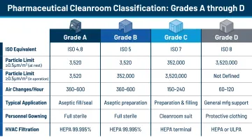
Manufacturing activities determine required grades. Aseptic fill-finish requires Grade A/ISO 5 conditions, while oral solid dosage manufacturing typically operates in Grade D/ISO 8 environments. The layout must physically enforce these grade boundaries through airlocks, pressure cascades, and dedicated HVAC systems.
Design Qualification (DQ)
Design Qualification is the formal process for documenting that facility design meets GMP user requirements. ICH Q7 defines it as "documented verification that the proposed design of the facilities, systems, and equipment is suitable for the intended purpose."
Those grade boundaries established during classification must be captured in DQ before a single wall goes up. DQ marks the first step in the validation lifecycle (DQ → IQ → OQ → PQ) and must be completed before construction begins to satisfy regulatory expectations.
Surface Materials and Finishes
FDA auditors inspect surface materials, finishes, and room geometry as directly as they inspect batch records. Required specifications include:
- Coved corners to eliminate particle accumulation points
- Seamless flooring systems
- Non-particle-shedding materials
- Cleanable, non-porous surfaces
- Smooth, hard surfaces in aseptic areas per 21 CFR 211.42(c)(10)
Getting these details wrong during design — rather than catching them in construction — is where facilities accumulate costly inspection findings.
Key Functional Zones in a Pharmaceutical Manufacturing Plant
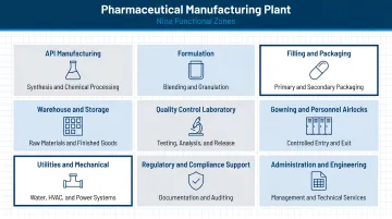
Every pharmaceutical plant layout must include clearly defined functional zones, each with distinct environmental controls and access requirements. Getting zone boundaries wrong early in design tends to create cascading problems — from HVAC conflicts to failed inspections — so understanding what each zone needs before construction begins is critical.
Primary Functional Zones
- Raw Material Receiving and Quarantine — Physically or electronically segregated to meet 21 CFR 211.80(d), with clear lot status identification (quarantined, approved, or rejected)
- Dispensing and Weighing — Controlled environments for measuring and preparing raw materials, requiring precise environmental monitoring and batch documentation
- Manufacturing Suites — Process-specific areas for granulation, blending, compression, coating, or sterile fill-finish; environmental classification depends on dosage form and contamination risk
- In-Process QC — Sampling and testing areas accessible from manufacturing without compromising cleanroom classification
- Packaging — Separate zones for primary and secondary operations, each with appropriate environmental controls
- Finished Goods Storage — Temperature-controlled warehousing with distinct areas for quarantined, approved, and rejected product
- QC Laboratory — Chemistry and microbiology labs separated from manufacturing, positioned for sample access without disrupting classified areas; includes dedicated stability storage
- Utilities and Mechanical — Houses purified water systems, HVAC equipment, compressed air, nitrogen, and other critical utilities
- Personnel Change Areas — Gowning rooms sized for peak traffic, designed as progressive airlocks from unclassified to classified space
Zone Segregation Requirements
Defining zones on a floor plan is only part of the work. How those zones are physically and mechanically separated determines whether the design holds up under an FDA inspection. Segregation is achieved through:
- Physical separation of potent compound handling areas
- Dedicated airlocks between classified and unclassified zones
- Separate HVAC systems for different classification areas
- Controlled access points with badge readers or interlocks
One requirement stands apart from design choices: 21 CFR 211.42(d) mandates that penicillin operations use entirely separate facilities. This isn't a layout preference — it's a non-negotiable regulatory line.
When architecture, process engineering, HVAC, and controls teams coordinate zone planning together from the start, design conflicts that surface late in construction — and cost the most to fix — are caught early in the process instead.
Designing for Material Flow, Personnel Movement, and Contamination Control
Effective pharmaceutical layout design integrates three interdependent systems: how materials move through the facility, how personnel navigate it, and how contamination is physically prevented at every boundary. Each subsystem reinforces the others — a gap in any one creates regulatory and product quality risk.
Unidirectional Flow Principle
Raw materials enter, move through production stages, and exit as finished product in one direction. Personnel follow separate, defined pathways that do not intersect with material flows. 21 CFR 211.42(b) requires this flow design to prevent contamination. Bidirectional or cross-traffic patterns introduce both contamination risk and GMP compliance exposure.
Airlock and Pressure Cascade Systems
Airlocks enforce contamination boundaries at every zone transition:
Positive Pressure Cascades: Higher-grade rooms maintain higher pressure than adjacent lower-grade spaces, protecting product from environmental ingress. This configuration is standard in most oral solid and sterile manufacturing areas.
Negative Pressure Cascades: Used for potent or hazardous compounds, where containment — not product protection — is the priority. These prevent airborne migration into adjacent spaces.
EU GMP Annex 1 Section 4.14 specifies minimum 10 Pascals pressure differential between adjacent rooms of different grades, with continuous monitoring and alarms. HVAC design must include calibrated differential pressure sensors with documented alert systems.
Personnel Gowning and Change Area Design
Progression from unclassified to classified areas follows a defined sequence:
- Dirty corridor (street clothes)
- Gowning room (donning cleanroom garments)
- Clean corridor (access to manufacturing)
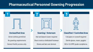
EU GMP Annex 1 Section 4.13 requires interlocking systems for airlocks leading to Grade A and Grade B areas—entry and exit doors must not open simultaneously. Gowning areas must be sized to handle peak personnel traffic without creating bottlenecks.
Personnel flow establishes the human boundary; material transfer systems define the physical one. Both require dedicated space allocations that are frequently underestimated.
Material Transfer Mechanisms
Material transfer systems each carry distinct spatial requirements:
- Pass-through hatches: Simple transfer between adjacent rooms
- Rapid transfer ports (RTPs): Closed transfer systems for potent compounds, maintaining containment
- Material airlocks: Dual-door chambers with interlocks
- Dedicated transfer corridors: Separate circulation paths for materials
Underestimating space for transfer systems — particularly RTPs and material airlocks — routinely forces costly redesigns during construction documentation.
Cross-Contamination Control and Room Adjacency
Incompatible products require dedicated or physically isolated suites:
- Beta-lactam antibiotics: 21 CFR 211.42(d) and 211.46(d) mandate separate facilities and completely separate HVAC
- Hormones and cytotoxics: EMA guideline EMA/CHMP/CVMP/SWP/169430/2012 requires dedicated facilities for substances with high sensitizing potential
- High-potency compounds: Containment strategies using isolators and RTPs per ISPE guidance
Map the facility's full product portfolio before finalizing layout — segregation requirements directly determine suite configuration, HVAC zoning, and room adjacency decisions.
HVAC, Utilities, and Environmental Control Systems
HVAC as Process-Critical Infrastructure
HVAC systems in pharmaceutical facilities are not building services—they are process-critical infrastructure. ISPE reports that HVAC consumes 50-80% of energy in a typical clean manufacturing facility.
Key HVAC Design Elements:
- Dedicated air handling units (AHUs) per cleanroom classification zone
- HEPA filtration (H14 filters for Grade A/B areas)
- Air change rates sufficient to achieve particle limits within less than 20 minutes per EU GMP Annex 1 Section 4.29
- Floor-to-ceiling height requirements to accommodate ductwork and plenums
- Pressure differential monitoring with continuous alarming
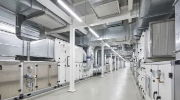
EU GMP Annex 1 requires HEPA filter integrity testing every 6 months for Grade A/B and every 12 months for Grade C/D.
Critical Utility Systems
HVAC is only one layer. Utility systems must be planned in parallel — routing decisions made late in design regularly force costly structural and layout changes:
- Purified Water (PW) and WFI: USP Chapter <1231> sets microbiological action limits — WFI at 10 CFU per 100 mL, Purified Water at 100 CFU per mL. Design requirements include thermal sanitization at minimum 80°C and dead leg ratios of 6:1 or less.
- Clean Steam: Required for sterilization-in-place (SIP) systems and any direct product contact applications.
- Compressed Air and Nitrogen: Process gases requiring dedicated filtration, drying, and distribution networks sized for peak demand.
Utility routing directly affects room layouts, ceiling heights, and structural loads. Deferring these decisions past schematic design typically means re-coordinating finished architectural drawings — an expensive and schedule-threatening rework.
Building Management and Monitoring Systems
GMP regulations require continuous environmental monitoring:
- Particle counts: Continuous monitoring in Grade A for the full duration of critical processing (EU GMP Annex 1 Sections 9.16-9.17)
- Differential pressure: Continuously monitored and recorded with alarm systems (Section 4.16)
- Temperature and humidity: Controlled and monitored to support cleanliness standards
- Viable monitoring: Continuous viable air monitoring in Grade A during critical processing
The layout must incorporate sensor placement, data logging infrastructure, and alarm systems—all qualified as part of the validation program.
Scalability, Flexibility, and Common Design Pitfalls to Avoid
Designing for Future Scalability
Designing for growth during initial concept reduces the cost and disruption of future expansions:
- Modular cleanroom construction supports demand scaling, process reconfiguration, and phased expansion without major structural rework (per ISPE guidance)
- Oversized utility stub-outs — pre-installed connections for future water loops, electrical services, and compressed air — allow seamless system growth
- Structural bays sized for future equipment reduce costly modifications during later phases
- Designated expansion zones in the master plan protect long-term layout flexibility
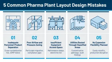
These scalability strategies only deliver value when the foundational design avoids the most common planning failures. Here's where pharmaceutical plant layouts most often go wrong.
Most Common Pharmaceutical Plant Layout Mistakes
- Undersized gowning and airlock areas create peak-traffic bottlenecks, forcing GMP-compromising workarounds
- Labs positioned too far from manufacturing increase contamination risk and slow in-process testing turnaround
- Overlooked equipment installation and maintenance corridors make it impossible to service or replace equipment without major facility disruption
- Insufficient ceiling heights for process equipment, ductwork, and utilities force expensive mid-project redesigns
- Missing GMP design intent documentation in DQ packages leaves validation gaps that create regulatory exposure
Engaging a firm like Hixson early — one with 75+ years of cGMP facility experience and 20 integrated in-house disciplines — gives manufacturers a coordinated design process where scalability planning and pitfall avoidance happen in parallel, not as afterthoughts.
Frequently Asked Questions
What is GMP design of pharmaceutical facilities?
GMP design means configuring a pharmaceutical facility so its physical layout, materials, and systems inherently support Good Manufacturing Practice compliance. This covers room finishes, air classification, flow patterns, and the documentation trail required by FDA and international regulators.
What are the key functional zones required in a pharmaceutical plant layout?
A complete pharmaceutical plant requires these functional zones:
- Raw material receiving and quarantine
- Dispensing and weighing
- Manufacturing suites
- In-process QC and sampling
- Packaging and labeling
- Finished goods storage
- QC laboratory and utility areas
- Personnel gowning and change rooms
Each zone carries distinct environmental classification and access control requirements.
How does material flow affect pharmaceutical plant design?
Unidirectional material flow prevents cross-contamination, reduces handling errors, and is a GMP requirement under 21 CFR 211.42(b). Poor flow planning forces materials to cross personnel paths or re-enter completed process zones, creating both compliance and efficiency problems.
What cleanroom classifications apply to pharmaceutical manufacturing?
ISO 5-8 classifications (EU GMP Grade A-D equivalents) apply depending on manufacturing activity. Aseptic fill-finish requires Grade A/ISO 5 conditions, while general oral solid dosage manufacturing typically operates in Grade D/ISO 8 environments. The layout must physically enforce these boundaries through airlocks and pressure cascades.
What is the difference between greenfield and brownfield pharmaceutical facility design?
Greenfield design starts from an empty site with full design freedom but longer timelines and higher initial capital. Brownfield involves retrofitting an existing building, potentially offering faster occupancy but carrying additional GMP risk because existing structural and utility constraints may compromise optimal flow and zone separation.
How long does it take to design a pharmaceutical manufacturing facility?
Timelines depend on facility size, complexity, and dosage form. A typical new pharmaceutical plant design process — from concept through construction documents — ranges from 18 months to several years, with more complex sterile manufacturing facilities trending toward the longer end.