Introduction
Cleanroom HVAC is the purpose-engineered system responsible for controlling air cleanliness, temperature, humidity, and pressure within a controlled environment to meet strict contamination standards. The definition is straightforward. The engineering behind it is not.
For engineers, facility managers, and project leads in pharma/biotech, medical device, semiconductor, and food & beverage industries, cleanroom HVAC directly shapes compliance outcomes, product quality, and qualification timelines. Get the design right and the facility qualifies. Get it wrong and rework costs compound fast.
According to ASHRAE, cleanrooms require 15–600 air changes per hour — compared to 3–12 ACH in conventional commercial spaces. That gap exists because cleanroom HVAC isn't about comfort — it's about maintaining particle counts, pressure differentials, and microbial limits tight enough to protect product integrity and meet regulatory requirements.
This guide covers how cleanroom HVAC works, the four core design principles, key system components, and the most common design mistakes that lead to costly rework or failed qualification.
Key Takeaways
- Cleanroom HVAC controls airborne particle counts — not just temperature and comfort
- The four design pillars: air change rate, airflow pattern, filtration efficiency, and pressure differentials
- ISO 14644-1:2015 defines particle cleanliness from ISO 1 (strictest) to ISO 9
- Core hardware includes HEPA/ULPA filters, air handling units, and pressure cascade systems
- Design errors in air changes, equipment placement, or pressure balancing routinely trigger classification failures and costly shutdowns
What Is Cleanroom HVAC and How Does It Differ from Conventional Systems?
Standard HVAC conditions air for occupant comfort. Cleanroom HVAC is engineered to achieve and sustain a defined airborne particle count — and that single distinction drives every design decision downstream.
ASHRAE data puts conventional commercial spaces at 3–12 ACH. Cleanrooms operate at 15–600 ACH depending on ISO classification and airflow pattern. An ISO Class 5 unidirectional room and an ISO Class 8 packaging area are both "cleanrooms," but their HVAC requirements are fundamentally different.
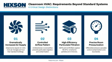
Four Requirements That Go Beyond Standard HVAC
Cleanroom HVAC must fulfill four requirements that conventional systems don't address:
- Dramatically increased air supply — to dilute and remove particles generated by people, equipment, and processes
- Controlled airflow pattern — unidirectional (laminar) flow for critical zones, turbulent for lower classifications
- High-efficiency particulate filtration — HEPA at minimum, ULPA for more stringent applications
- Precise room pressurization — positive pressure to exclude contaminants, negative pressure to contain hazardous materials
Failing any one of these doesn't just degrade performance — it can cause a classification breach and trigger requalification.
AHU vs. Full HVAC System
Because cleanroom HVAC spans all four requirements above, early project scoping needs to account for the full system — not just the most visible piece. The AHU (air handling unit) heats, cools, and filters air, but it's one component within a larger infrastructure that includes ductwork, diffusers, HEPA terminal units, return air paths, pressure controls, and monitoring systems.
Projects scoped around the AHU alone routinely overlook return air paths and pressure monitoring — two components that directly determine whether a room achieves and holds its classification during qualification testing.
Core Principles of Cleanroom HVAC Design
Airflow Rate and Pattern
Air change rate calculations depend on ISO classification target and airflow strategy:
- ACH method — used for ISO 6–9 rooms where turbulent (non-unidirectional) mixing is acceptable
- Face velocity method — used for ISO 1–5 rooms with unidirectional airflow
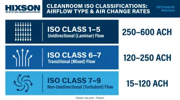
ASHRAE-supported ACH ranges by classification:
| ISO Class | Airflow Type | ACH Range |
|---|---|---|
| ISO 1–5 | Unidirectional | 250–600 ACH |
| ISO 6–7 | Transitional | 120–250 ACH |
| ISO 7–9 | Non-unidirectional | 15–120 ACH |
For unidirectional designs, EU GMP Annex 1 specifies air speed of 0.36–0.54 m/s at the working position, with measurement locations justified in the qualification protocol. A 2023 systematic review found evidence that 0.30–0.33 m/s can achieve contamination control in some configurations — so face velocity targets require validation against actual particle generation data for each specific configuration, not blanket application of published ranges.
Three airflow pattern types:
- Unidirectional (laminar) — air moves in a single parallel direction, sweeping particles away from critical zones; required for ISO 1–5
- Non-unidirectional (turbulent) — high-volume mixing for lower-classification rooms (ISO 6–9)
- Mixed — used in transitional zones or multi-activity spaces where both approaches are needed in different areas
Pressure Differentials and Cascading Pressure
Pressure differential design establishes the containment logic for the entire facility.
Positive pressure keeps contaminants out — standard for most pharmaceutical, biotech, and semiconductor cleanrooms. Negative pressure contains hazardous materials inside — required for USP 800 hazardous drug handling and certain containment applications.
EU GMP Annex 1 sets a minimum 10 Pa differential between adjacent cleanrooms of different grades. Airlocks are required for personnel and material movement between grades, and airlocks leading to Grade A and B areas need interlocking systems to prevent simultaneous door opening.
In multi-room cleanroom suites, pressure must cascade: the cleanest room sits at the highest relative pressure, with each adjacent zone stepping down. In hazardous containment suites, this logic inverts — the contained space is at the lowest pressure, and each adjacent zone steps up.
Door events are a real failure mode. A 2023 study of pharmaceutical cleanrooms tested pressure differentials of 5–25 Pa and airlock door delays of 6–36 seconds. Door operation and personnel entry caused measurable smoke invasion across thresholds — and higher initial pressure differentials improved containment. Pressure balancing specifications — differential magnitudes, airlock timing, interlock logic — belong in the mechanical design documents, not resolved during commissioning when corrections are far more expensive.
Filtration Strategy
Pressure control manages where air goes; filtration controls what that air carries. Where pressure differentials limit particle migration between zones, filtration removes what the air change rate can't dilute fast enough.
- HEPA filters — 99.97% efficient at 0.3 microns, required for aseptic processing areas under FDA 21 CFR Part 211
- ULPA filters — classified by Most Penetrating Particle Size (MPPS) per ISO 29463; used for more stringent semiconductor and pharmaceutical applications
- Pre-filters — important but frequently underspecified; protect expensive terminal filters and extend service life substantially
Terminal HEPA or ULPA filters belong as close to the supply point as possible — mounted in the ceiling directly above critical zones — so that post-filter ductwork doesn't reintroduce particles.
Pre-filters should be positioned upstream in the AHU to capture coarse particles before they reach terminal filtration. Skipping or undersizing pre-filters is one of the fastest ways to inflate long-term maintenance costs.
Temperature and Humidity Control
Temperature and humidity affect more than occupant comfort in cleanrooms:
- Uncontrolled humidity promotes microbial growth and can degrade pharmaceutical compounds
- Low humidity induces electrostatic discharge — a critical risk in semiconductor and electronics environments
- Temperature variation affects product stability, process accuracy, and personnel fatigue in gowned environments
Humidity control systems — humidifiers, dehumidifiers, desiccant wheels — must be integrated into the AHU design from the start. Adding them after mechanical design is complete typically forces undersized coil selections and control sequence conflicts that require rework — a far more expensive problem than specifying correctly upfront.
Key Components of a Cleanroom HVAC System
Air Handling Unit (AHU)
The AHU is the central processing unit. It houses:
- Cooling coils and heating coils (hot water or electric)
- Humidification and dehumidification equipment
- Variable-speed supply fans
AHU sizing must account for internal heat loads from people, equipment, and lighting — not just envelope conditions. Variable speed drives allow occupancy-based setback, which matters significantly given that cleanroom HVAC can represent 36%–67% of total facility energy consumption, per ISPE benchmarking data.
Ductwork, Diffusers, and Plenums
Ductwork design directly shapes what happens inside the room:
- Straight duct runs minimize static pressure buildup
- Smooth internal surfaces prevent particle accumulation between cleanings
- Insulated ducts prevent condensation and associated microbial risk
- All joints must be tightly sealed — unfiltered air infiltration through leaky ductwork undermines terminal filtration
Ducted vs. plenum systems: Ducted systems offer better control for smaller rooms and negative-pressure containment. Plenum-based ceiling systems are more efficient for larger rooms with distributed HEPA arrays. The choice affects both construction cost and long-term maintainability.
Fan Filter Units (FFUs) and Terminal HEPA Filtration
FFUs are self-contained ceiling-mounted units that draw recirculated air through integral HEPA filters, delivering low-turbulence air directly into the cleanroom.
| Approach | Advantages | Best For |
|---|---|---|
| FFU-based design | Flexible, scalable, modular | Modular cleanrooms, phased buildouts |
| Centralized AHU + terminal HEPA | Energy-efficient at scale, filter maintenance outside room | Large fixed cleanrooms |
The filtration approach decision belongs in schematic design — it cascades directly into structural loading calculations, electrical distribution layout, and maintenance access planning. On projects like the Unither Pharmaceuticals BFS manufacturing expansion in Rochester, New York, Hixson's pharma and biotech teams lock in this choice before detailed engineering begins precisely because reversing it mid-design is costly.
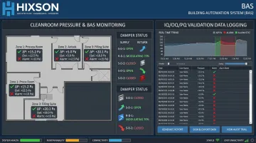
Pressure Controls and Monitoring Systems
Compliant operation in FDA-regulated and ISO-certified environments requires active, automated pressure control — not one-time manual balancing at commissioning. That means:
- Pressure sensors at each room boundary
- Automated dampers that respond to real-time differential readings
- Building automation system (BAS) integration with alarm setpoints for out-of-range conditions
- Data logging that feeds directly into IQ/OQ/PQ validation documentation and ongoing environmental monitoring programs
Hixson's Controls & Automation team integrates these monitoring systems as part of cleanroom design, not as a separate commissioning add-on. The department brings more than 75 years of combined experience to that work, which means validation documentation requirements inform the monitoring architecture from day one.
Make-Up Air and Exhaust Systems
Make-up air (fresh outdoor air) replaces exhaust and maintains positive pressurization. The proportion relative to recirculated air involves a direct tradeoff: more make-up air improves contaminant dilution but increases cooling and heating loads.
Getting that balance right depends on several factors. Key design rules:
- Minimum make-up air per operator prevents CO₂ buildup in occupied gowning and work areas
- Exhaust air from hazardous or negative-pressure rooms must discharge to the outside — never recirculated
- Exhaust systems for containment spaces require dedicated ductwork with no mixing points
Common Cleanroom HVAC Design Mistakes
Underestimating Internal Heat and Particle Loads
HVAC systems sized purely on room volume — without accounting for actual occupancy and equipment heat dissipation — consistently underperform at qualification. Three internal sources routinely get underestimated:
- Process equipment in pharmaceutical manufacturing, which generates significant heat under operating conditions
- Operators in full gowning, who add meaningful metabolic load during shifts
- Lighting in controlled environments, which contributes to the total heat gain
Completing a rigorous internal heat load analysis before design finalization is essential. Projects that skip this step typically discover the gap during performance qualification, when mechanical corrections require tearing into completed work.
Poor Equipment Placement Relative to Airflow
Placing heat-generating process equipment, gowning areas, or high-traffic pathways between HEPA supply and return air creates turbulence and particle accumulation in critical zones.
Best practice: locate the dirtiest workstations nearest to return air vents. Equipment placement that looks acceptable on a floor plan can produce contamination hot spots that only appear during airflow visualization studies.
Model airflow using CFD (computational fluid dynamics) tools during design — particularly for ISO Class 5–7 spaces where unidirectional or semi-unidirectional flow is required.
Treating Pressure Balancing as a Commissioning Step
Pressure balancing is a design decision. Projects that defer it to commissioning routinely encounter:
- Under-pressurization between adjacent rooms due to undersized dampers or insufficient make-up air
- Door seal gaps that allow pressure equalization during door-open events
- Transient pressure reversals during rapid door-opening, where door speed and angle directly affect contamination transfer across the threshold
The fix is to design for the worst-case door event, not the steady-state differential.
Designing for Initial Qualification, Not Ongoing Operation
Systems designed without accessible filter housings, labeled isolation valves, or adequate ceiling and plenum access panels create operational bottlenecks that surface months after handover.
ISO-classified HVAC systems require:
- Regular filter replacement (pre-filters more frequently than terminal HEPA)
- Periodic sensor calibration and verification
- Duct inspections at defined intervals
- Rebalancing after process changes
Planning for these activities during design — not after handover — means specifying adequate access panel spacing, locating isolation valves where technicians can reach them, and confirming that filter change-out paths don't compromise adjacent classified areas.
When Your Cleanroom HVAC Project Needs a Multi-Discipline Engineering Team
Scenarios That Exceed Mechanical Contractor Scope
Cleanroom HVAC complexity outpaces what a single-discipline contractor can reliably deliver when:
- The project involves multi-room ISO-classified suites with cascading pressure requirements
- The facility must comply with FDA 21 CFR Parts 210/211, EU GMP Annex 1, or USP 797/800
- The cleanroom must be integrated into an existing operating facility without disrupting ongoing production
- The regulatory pathway requires IQ/OQ/PQ documentation tied directly to HVAC system design
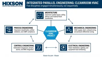
What Multi-Discipline Coordination Actually Requires
Mechanical, electrical, process, architecture, and controls engineering cannot work in sequence on a cleanroom project. They must work in parallel, because each discipline's decisions constrain the others:
- Mechanical engineers size AHUs and design pressure cascades — but need heat and particle load inputs from process engineers first
- Process engineers specify equipment — but equipment placement affects airflow modeling
- Electrical engineers power AHUs, FFUs, controls, and monitoring — but panel locations affect ductwork routing
- Architects design envelopes and door placements — but traffic flow patterns affect contamination risk zones
- Controls engineers design BAS integration and alarm setpoints — but need to be involved during mechanical design, not after
The Construction Industry Institute's research on Front End Planning supports this: effective early-phase coordination improves cost performance, schedule predictability, and operational outcomes on complex projects. Sequential handoffs between disciplines are a primary driver of late-stage changes and rework.
Hixson's Integrated Approach
Hixson brings mechanical, electrical, process, architecture, and controls engineering under one roof — and engages all disciplines from the start of a project, not after the mechanical scope is already drafted. That means technical requirements for temperature, humidity, filtration, and pressurization are defined collaboratively, with each discipline informing the others in real time.
That parallel engagement continues from URS definition through commissioning and qualification validation (CQV).
Hixson's Science & Technology and Pharma & Biotech practices have delivered controlled environments across North America, including the Eurofins Genomics 72,000 SF cGMP genomics facility in Louisville and the PETNET Solutions radiopharmaceutical manufacturing facility requiring tightly controlled environments for cyclotron operations.
Documentation produced through Hixson's integrated process supports IQ/OQ/PQ validation in alignment with FDA and EU GMP requirements.
If your project involves classified environments, regulatory submission timelines, or integration into an active facility, the right time to engage a full-service A&E team is before scope is set — not after the first coordination problem surfaces.
Frequently Asked Questions
How does cleanroom HVAC work?
Cleanroom HVAC circulates air at high rates (15–600 ACH depending on ISO class) through HEPA or ULPA terminal filters, maintains pressure differentials between adjacent zones, and precisely controls temperature and humidity. The system is engineered to achieve and sustain a defined airborne particulate cleanliness level — not just occupant comfort.
What are the principles of cleanroom design?
The four core principles are: controlling air change rates to match the target ISO classification, directing airflow patterns (unidirectional for ISO 1–5, turbulent for ISO 6–9), maintaining room pressurization through cascading pressure differentials, and achieving filtration efficiency through properly staged HEPA/ULPA systems.
What are the key components of a cleanroom HVAC system?
The primary components are air handling units (AHUs), HEPA or ULPA terminal filters (or fan filter units), ductwork and plenums, pressure sensors and automated damper controls, building automation systems (BAS) for real-time monitoring, and dedicated make-up air and exhaust systems.
What are the ISO standards for HVAC in cleanrooms?
ISO 14644-1:2015 is the primary classification standard, defining maximum allowable particle counts by ISO class (1–9). ASHRAE's Design Guide for Cleanrooms, IEST recommended practices (including IEST-RP-CC012), and EU GMP Annex 1 provide supplemental methodology for HVAC design, testing, and validation.
What is the FDA standard for cleanroom?
The FDA does not publish a single cleanroom standard. It references ISO 14644-1 for classification and enforces GMP requirements through 21 CFR Parts 210/211 (pharmaceutical manufacturing) and 21 CFR Part 820 (medical devices). HVAC design must satisfy both classification targets and GMP documentation requirements, including validation support.
How much does it cost to build a cleanroom?
Costs vary by ISO classification, size, region, and HVAC complexity — and HVAC typically accounts for 36%–67% of total facility energy costs once operational, per ISPE benchmarking. Engage a qualified A&E team early to define scope and generate defensible cost estimates before design commitments are made.