Introduction
Water is the most widely used raw material in pharmaceutical manufacturing , and it's among the most consequential to get wrong. A single batch contaminated by inadequate water quality can trigger recalls, regulatory action, and direct patient harm. Yet pharmaceutical RO plant design is routinely underestimated at the facility planning level.
A pharmaceutical RO plant is a multi-stage water purification system built around reverse osmosis membranes, engineered specifically to produce the high-purity water grades required for drug manufacturing. Unlike standard commercial filtration, it operates as a validated, GMP-controlled treatment train with direct compliance implications.
This guide is written for pharmaceutical facility engineers, biotech plant managers, and A&E teams designing or evaluating purified water systems. It covers how the treatment train works, which engineering decisions carry the most compliance risk, and where designs commonly fail.
Key Takeaways
- RO plants produce USP Purified Water (PW) or serve as WFI precursor systems by rejecting dissolved solids, organics, microorganisms, and endotoxins
- Compliant systems require a validated treatment train: pre-treatment → RO membrane stage → post-RO polishing
- USP and FDA define hard quality limits: ≤500 µg/L TOC, ≤100 CFU/mL for PW, ≤10 CFU/100 mL for WFI
- Membrane selection is only one piece — piping material, loop hydraulics, storage sizing, and automation design carry equal compliance weight
- Dead legs, undersized capacity, and poor sanitization provisions are the top causes of failed audits and costly retrofits
What Is a Pharmaceutical RO Plant?
A pharmaceutical RO plant is an engineered water purification system that uses semipermeable membranes to reject dissolved ions, organics, bacteria, and endotoxins from feedwater, producing water suitable for drug manufacturing. The distinction from industrial RO lies in three areas: materials of construction, pre- and post-membrane treatment, and the documentation required to satisfy regulatory inspection.
Standard industrial RO targets scale control and equipment protection. Pharmaceutical RO must satisfy pharmacopeial monographs, survive regulatory inspection, and require materials that won't introduce contamination.
The Regulatory Boundary
Three global pharmacopeias govern pharmaceutical water quality:
- USP: Purified Water and Water for Injection monographs, supported by <1231>, <643>, and <645>
- Ph. Eur.: Monograph 0008 for Purified Water, 0169 for Water for Injections
- JP XVII: Purified Water, Purified Water in Containers, Water for Injection, and WFI in Containers
Water Grades the RO Plant Supports
- Purified Water (PW): Covers general manufacturing, formulation, equipment cleaning, and analytical use; produced by RO with post-RO polishing
- WFI precursor: RO acts as the high-rejection primary stage before final polishing to Water for Injection quality, a route permitted under both USP and Ph. Eur. since April 2017
The water grade targeted determines how the RO plant is configured upstream and downstream of the membranes.
How a Pharmaceutical RO Plant Works
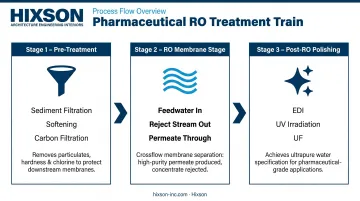
The pharmaceutical RO treatment train moves water through three sequential stages: pre-treatment conditions feedwater for the membranes; the RO stage rejects the bulk of dissolved contaminants; post-RO polishing removes residual ions, organics, and microorganisms to reach final quality targets.
Throughout the process, pressure, flow, temperature, and conductivity are monitored continuously via PLC-based automation. Every parameter is tracked in real time — not sampled periodically.
Pre-Treatment Stage
Pre-treatment protects the membranes and determines how well the rest of the system performs. Skipping or undersizing it is one of the most common causes of premature membrane failure.
Core pre-treatment steps:
- Multimedia or sediment filtration reduces turbidity and suspended solids before water reaches the membranes
- Water softening or antiscalant dosing prevents hardness minerals from crystallizing on membrane surfaces
- Activated carbon or catalytic carbon filtration removes free chlorine and chloramines — the final chemical threat to polyamide membranes
That last step is mandatory per membrane manufacturer guidance. DuPont FilmTec states that free chlorine must be removed before polyamide membranes, and that chloramines are not recommended because they can release free chlorine that slowly degrades thin-film composite membranes. Continuous ORP or free-chlorine monitoring is recommended to verify removal — not just periodic testing.
RO Membrane Stage
A high-pressure pump forces pre-treated feedwater across the semipermeable membrane. Dissolved solids, organics, and microorganisms concentrate into a reject stream; purified permeate passes through.
Membrane performance data from Hydranautics/Nitto TAB 118:
- 99.0–99.8% salt rejection for polyamide RO membranes
- >4-log (>99.99%) removal of viruses and bacteria
Pharmaceutical systems may be single-stage (adequate for moderate recovery) or multi-stage with booster pumps between stages, depending on required permeate flow and recovery targets.
Recovery rates are sized to balance water efficiency against membrane fouling risk. The specific target depends on feedwater chemistry and system configuration, and should be confirmed with the membrane manufacturer and ISPE guidance during detailed design.
Post-RO Polishing Stage
RO permeate is not finished product. Post-treatment technologies bring it to pharmacopeial quality:
- Electrodeionization (EDI) is a continuous, chemical-free process that removes ionized and ionizable species from RO permeate. DuPont EDI systems can produce resistivity approaching 18 MΩ·cm — the threshold needed to meet USP <645> conductivity targets
- UV irradiation destroys residual microorganisms and reduces TOC
- Ultrafiltration (UF) acts as a final barrier against endotoxins and biofilm fragments; 10 kDa membranes are documented for WFI endotoxin removal applications
The right combination of these technologies depends on target water grade (PW vs. WFI precursor) and feedwater characteristics established during pre-design testing.
Critical Engineering Design Factors
Membrane performance gets the attention. These factors determine whether the system passes an audit.
Piping Material and Dead Leg Elimination
Sanitary-grade 316L stainless steel is the standard for pharmaceutical RO distribution loops. All welds should be orbital-welded, with electropolished interior surfaces to prevent corrosion and inhibit biofilm adhesion.
Dead legs — stagnant pipe sections where microbial growth occurs — are a non-negotiable design target. The FDA defines dead legs as unused pipe portions exceeding six pipe diameters. ASME BPE tightens this further: the current target dead leg ratio is L/D ≤ 2:1. An FDA warning letter issued to Profounda, Inc. in February 2023 cited a water system that included a dead leg and was not continuously circulating — a textbook GMP failure that triggered enforcement action.
Non-sanitary ball valves are another documented problem. The FDA's high-purity water guide identifies them as harboring stagnant water and microorganisms. Valve selection is a design decision, not a procurement afterthought.
Storage and Distribution Loop Design
Purified water is stored in jacketed, vented, and passivated stainless steel tanks sized to buffer production demand — but sizing carries risk in both directions. Oversized storage creates excessive hold time; extended stagnation increases microbial load.
The loop itself must be continuously recirculating at all times. Turbulent flow prevents biofilm formation and keeps water quality consistent between use points. A one-way (dead-end) distribution system is functionally a dead leg across the entire loop — the FDA's high-purity water guide explicitly identifies this as unacceptable.
Water quality at the point of use depends on both the loop design and the instrumentation monitoring it throughout the circuit.
Automation and Continuous Monitoring
Pharmaceutical RO systems require online instrumentation for:
- Conductivity (per USP <645>)
- TOC (per USP <643>)
- Temperature
- Flow
These feed into a validated PLC/SCADA system that logs data and generates out-of-specification alerts. Conductivity monitoring alone is insufficient for microbiological control — the FDA notes that conductivity meters provide no microbiological quality information. Microbial monitoring requires separate sampling protocols with defined alert and action limits.
Control system design directly affects validation burden. Systems built with 21 CFR Part 11-compliant data integrity features — audit trails, access controls, validated electronic records — reduce audit risk substantially.
This is where integrated engineering across process, controls, and automation disciplines matters. Hixson's controls and automation engineers work alongside plumbing and process engineers throughout the project, designing the water system and its control architecture as a single coordinated scope — which reduces reconciliation issues during commissioning and simplifies the validation package.
Sanitization Provisions
Sanitization capability must be engineered in from the start. Design elements include:
- Heat exchangers for hot water sanitization circuits
- Spray balls in storage tanks
- Valve configurations that allow sanitization loops without full system shutdown
- Materials rated for thermal or chemical sanitization cycles
EU GMP Annex 1 requires sanitization according to a predetermined schedule or after out-of-limit results. Chemical sanitization must be followed by validated rinsing and testing before the system returns to service. WFI systems are often maintained above 70°C continuously to suppress microbial growth.
Retrofitting sanitization provisions post-commissioning is expensive and sometimes structurally impossible — a consequence that's far easier to avoid at the design stage than to solve after construction.
Capacity Planning and Sizing
Systems sized only for current production volume become problems quickly. Design must account for:
- Peak simultaneous demand across all use points
- Redundant RO train capacity so maintenance doesn't stop manufacturing
- Storage volume that buffers demand without creating excessive hold time
- Seasonal feedwater variation (FDA water validation requires a full year of data to capture this)
Build growth capacity into the initial design. The right percentage depends on the facility's expansion plans, manufacturing schedule, and use-point count — ISPE Baseline Guide Vol. 4 provides the framework for these calculations during detailed engineering.
Regulatory Compliance and Validation
Primary Regulatory Frameworks
| Framework | What It Requires |
|---|---|
| USP <1231> | Water for Pharmaceutical Purposes — informational chapter defining appropriate water grades, treatment methods, and monitoring expectations |
| USP <643> | TOC limit of 500 µg/L (as limit response) |
| USP <645> | Conductivity limits by stage and temperature |
| FDA Process Validation Guidance (2011) | Lifecycle validation framework: design, qualification, continued process verification |
| EU GMP Annex 1 | WFI system design, qualification, continuous monitoring, sanitization, and endotoxin control requirements |
USP FAQs confirm that TOC and conductivity testing can be performed online or offline, provided the tested water is representative of the system at each point.
The Validation Sequence
The FDA's water validation approach uses phased sampling:
- Phase 1 (2–4 weeks, daily sampling): Establish baseline performance across operational modes
- Phase 2 (2–4 weeks, continued daily sampling): Demonstrate consistency after Phase 1 adjustments
- Phase 3 (1 year): Confirm consistent quality across seasonal feedwater variation
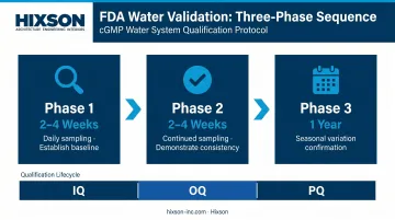
These phases sit within the broader IQ → OQ → PQ lifecycle. Installation Qualification (IQ) verifies the system was built as designed. Operational Qualification (OQ) demonstrates performance within specified parameters. Process Qualification (PQ) confirms consistent pharmacopeial-quality output over time.
Design documentation — P&IDs, equipment specifications, material certifications — forms the foundation of IQ. Build it with validation in mind from project inception, not as a retroactive exercise before the audit.
Monitoring Infrastructure as a Design Decision
Sample ports, their locations, and their accessibility are engineering decisions. Facilities that commission systems without adequate sampling access discover the problem during routine GMP monitoring — at which point the fix requires either replumbing or a permanently compromised monitoring program. Design the access in; don't retrofit it.
Common Design Mistakes
RO as a Standalone Solution
RO membranes reject 99.0–99.8% of dissolved salts and provide >4-log microbial removal — impressive numbers that mislead some facility teams into treating RO as sufficient on its own. It isn't. Without pre-treatment, membranes foul and fail prematurely. Without post-RO polishing (EDI, UV, UF), permeate doesn't reliably reach USP <643> TOC or <645> conductivity limits. The treatment train is the system, not the membrane.
Undersizing and Loop Hydraulics
Facilities sized only for current production routinely face two compounding problems as they grow:
- Insufficient RO capacity during high-demand periods, forcing manufacturing pauses
- Low-velocity zones in distribution loops that weren't hydraulically modeled during design
Low-velocity zones don't require a formal dead leg to create microbial hotspots — they just need flow rates below the turbulent threshold. These zones are difficult to remediate without replumbing. Hydraulic modeling is not optional for pharmaceutical distribution loops.
Validation Scope Misunderstood at Design Time
Equipment selected without considering its validation documentation trail creates mid-project problems. Common failure points include:
- Instruments lacking calibration traceability
- PLCs without Part 21 CFR Part 11-compliant audit trail capability
- Materials missing proper certifications
Each of these requires either replacement or extensive compensating controls — both expensive and schedule-threatening.
Teams that integrate validation planning into equipment selection from the start avoid this entirely. Hixson coordinates process, plumbing, and controls engineering alongside validation documentation support from URS through IQ/OQ/PQ — keeping all disciplines aligned before late-stage rework becomes the only option.
Conclusion
A well-designed pharmaceutical RO plant functions as a validated treatment train — fully integrated into the facility's piping, automation, and sanitation systems. When designed correctly, it reliably produces water meeting USP and FDA quality standards across the full range of operational conditions, from daily manufacturing to seasonal feedwater shifts to post-maintenance sanitization cycles.
The decisions that determine long-term compliance outcomes are made early: piping material selection, loop hydraulics, storage sizing, control system architecture, and sanitization provisions. None of these can be effectively retrofitted.
For facilities planning new or upgraded pharmaceutical water systems, partnering with a firm like Hixson — with in-house expertise spanning plumbing systems, mechanical engineering, controls and automation, and cGMP documentation — ensures these decisions are made with full coordination, from concept through commissioning.
Frequently Asked Questions
What is the difference between Purified Water (PW) and Water for Injection (WFI) in pharmaceutical manufacturing?
PW is used for general manufacturing, formulation, and equipment cleaning, typically produced by RO with post-RO polishing to meet USP <643> and <645> limits. WFI requires higher purity with a strict endotoxin limit of 0.25 EU/mL and a microbial action level of 10 CFU/100 mL. Once limited to distillation, WFI can now be produced by membrane-based systems under updated USP and Ph. Eur. guidance (effective April 2017).
What regulatory standards apply to pharmaceutical RO plant design?
The primary references are USP <1231> (Water for Pharmaceutical Purposes), USP <643> (TOC), USP <645> (conductivity), FDA Process Validation Guidance (2011), and EU GMP Annex 1 for sterile manufacturing. These define water quality limits and establish the validation framework that system design must support from the earliest project phases.
What pre-treatment does a pharmaceutical RO system require?
Core pre-treatment steps include sediment or multimedia filtration to reduce turbidity, water softening or antiscalant dosing to control scaling, and carbon filtration to remove chlorine and chloramines before the RO membrane. The specific combination and sizing depend on feedwater chemistry analysis conducted prior to detailed design.
How is a pharmaceutical RO system validated?
Validation follows a phased approach: IQ verifies the system was built as designed; OQ demonstrates performance within specified parameters; PQ confirms consistent water quality over a defined period including seasonal variation. Design documentation generated during engineering forms the foundation of the entire validation package.
What piping materials are required for a pharmaceutical RO distribution system?
316L stainless steel with orbital welds and electropolished interior surfaces is the industry standard. ASME BPE provides guidance on acceptable dead leg ratios — the current target is L/D ≤ 2:1 — and on surface finish requirements for pharmaceutical-grade systems.
How often should a pharmaceutical RO system be sanitized?
Sanitization frequency is defined during validation based on microbial trend data. Most facilities schedule hot water or chemical sanitization routinely, with additional cycles required after maintenance events or out-of-specification microbiological results. Both frequency and method are design decisions that must be built into system capability from the outset.