Introduction
A GMP pharmaceutical facility can have a strong quality management system, validated processes, and well-trained staff — and still generate regulatory observations during an FDA or EMA inspection. Why? Because the building itself fails to support the quality program.
Physical design deficiencies are among the most cited issues in FDA warning letters. The agency cited Samson Pharmaceuticals under 21 CFR 211.42(c)(10)(i) for aseptic-processing areas that lacked smooth, hard, easily cleanable surfaces — a basic design requirement, not a procedural one.
What follows covers the architectural and engineering decisions that determine GMP compliance: layout and zoning, cleanroom HVAC, surface specifications, clean utilities, and qualification documentation. Get these right in design, and they support every quality program that follows. Get them wrong, and no amount of SOPs or training will fully compensate.
Key Takeaways
- GMP compliance starts with physical design — HVAC, zoning, surfaces, and utilities create the foundation that procedural controls build on
- Unidirectional flow of materials, personnel, and waste is non-negotiable — every corridor, airlock, and gowning sequence depends on getting it right at the design stage
- Pressure differential cascades must hold under dynamic operating conditions, not just during static commissioning tests
- Surface and finish specifications in classified areas involve material and detail decisions where common defaults will fail regulatory scrutiny
- Design documents serve as qualification evidence; gaps or inconsistencies in them become findings during FDA inspections
Core GMP Principles That Drive Facility Design
The Premises Obligation
21 CFR 211.42 states that buildings used for drug manufacture must be suitable in size, construction, and location to facilitate cleaning, maintenance, and proper operations. The regulation requires that drug product flow through facilities be designed to prevent contamination — and that separate or defined areas exist to prevent mix-ups.
WHO GMP takes the same position: premises must be located, designed, constructed, and maintained to suit the operations performed and to minimize errors, cross-contamination, and adverse quality effects.
This means designers carry direct regulatory obligations. Facility operators can't compensate procedurally for a building that wasn't designed right.
Quality by Design Applied to Facilities
ICH Q8(R2) establishes that quality must be built into products by design, not verified through testing afterward. That principle extends directly to manufacturing environments. When contamination controls, pressure relationships, and operational flows are engineered into the physical structure, the facility inherently supports the quality program.
When those elements are missing, SOPs and monitoring programs carry more weight than they should — and inspectors notice.
FDA and EMA inspectors evaluate facility design directly. During sterile drug inspections, FDA reviews room classifications, pressure differentials, airflow configurations, material flow logic, and surface condition as evidence of whether quality has been designed into the process.
Regulatory Landscape
The major frameworks designers must account for:
- FDA 21 CFR Parts 210/211 — performance-based requirements for buildings, ventilation, and contamination prevention
- EU GMP Annex 1 (2022) — detailed sterile manufacturing requirements covering cleanroom grades, pressure differentials, airflow visualization, and monitoring
- WHO GMP guidelines — premises and HVAC principles for international markets
- ISPE Baseline Guides — industry guidance (not regulations) covering facility design and commissioning and qualification
Specific requirements for air quality, pressure thresholds, and monitoring intensity differ by region and product type. Sterile injectables face substantially stricter requirements than oral solid dose — a distinction that shapes design scope and cost from the earliest project phases.
Facility Layout, Zoning, and Flow Design
Cleanroom Classification as the Zoning Foundation
EU GMP Annex 1 defines four cleanroom grades relevant to sterile manufacturing:
| Grade | At Rest (≥0.5 µm/m³) | In Operation (≥0.5 µm/m³) | Typical Use |
|---|---|---|---|
| A | 3,520 | 3,520 | Critical aseptic operations |
| B | 3,520 | 352,000 | Background to Grade A (open processing) |
| C | 352,000 | 3,520,000 | Less critical sterile operations |
| D | 3,520,000 | Not predetermined | Background support areas |
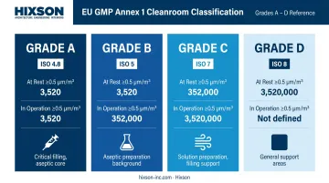
ISO 5 through ISO 8 classifications (per ISO 14644-1) correlate to EU Grades A through D. The product type — sterile injectables, oral solid dose, biologics — determines which grades are required and where. That determination drives every major zoning decision in the facility.
Unidirectional Flow
Raw materials, in-process goods, personnel, finished product, and waste must each follow defined, separated routes. No clean flow path should cross a potentially contaminated one.
This principle shapes:
- Corridor layout and directionality
- Airlock placement and sizing — with separate configurations for personnel vs. material transfers
- Gowning room adjacency to classified spaces
- Separate entry and exit routes for materials and personnel
EU GMP Annex 1 specifically requires that transfers into Grade A and B areas follow a unidirectional process.
Airlocks and Pressure Segregation
Airlocks provide physical separation between areas of different classifications. Annex 1 requires that airlocks minimize microbial and particulate contamination transfer and that personnel airlocks move staff through progressively cleaner spaces.
Key design requirements:
- Interlocked door systems so entry and exit doors cannot open simultaneously in Grade A/B airlocks
- Pass-through chambers for material transfer
- HVAC pressure relationships that reinforce the physical separation
Each of these requirements works together. Miss one — wrong size, wrong pressure relationship, missing interlock — and the result is a contamination pathway that no cleaning procedure can reliably close.
Cross-Discipline Coordination
Optimal layout requires architecture, process engineering, and mechanical/electrical disciplines working from a shared process flow model from the earliest design phases. When an integrated team works this way, layout decisions reflect operational reality. When disciplines work in sequence rather than parallel, pressure relationships and flow logic tend to conflict — and those conflicts surface late in design, when changes are expensive.
Hixson's Architecture and Process Layout teams coordinate across all 20 in-house disciplines from project kickoff, with integration beginning at the URS definition phase for pharmaceutical and biotech facility projects.
Cleanroom HVAC and Environmental Controls
Air Change Rates and Filtration
FDA's aseptic guidance states that ISO 8 supporting cleanrooms should achieve at least 20 air changes per hour. Annex 1 does not prescribe a universal ACH table — instead, it requires that air change rates be determined through qualification based on the contamination control strategy for each space.
HEPA filtration is required for Grade A and B areas. Supply and return air configurations must be designed to:
- Provide unidirectional airflow in critical zones
- Prevent contamination migration from lower to higher classification spaces
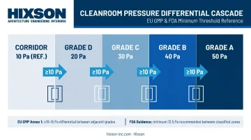
Pressure Differential Cascades
Positive pressure in higher-classification areas relative to adjacent lower-classification spaces is the primary mechanism for preventing particulate and microbial ingress.
- EU GMP Annex 1 specifies a minimum of 10 Pa between adjacent rooms of different grades
- FDA aseptic guidance recommends 10–15 Pa (approximately 0.05 inch water gauge)
HVAC systems must maintain these differentials under dynamic conditions — doors opening, personnel movement, equipment operation. A system that holds 15 Pa at steady state but drops below threshold when a gowning room door opens is not adequate.
Annex 1 requires continuous monitoring and recording of critical pressure differences, with a warning system for failures.
Environmental Monitoring Integration
Environmental monitoring systems must be built into the facility design, not added after construction. This includes:
- Particle counters positioned relative to air supply and return locations
- Temperature and humidity sensors appropriate to the room classification
- Differential pressure indicators at all classified boundaries
- Microbial sampling points at defined locations
- Alarm integration with building management systems
- Electronic monitoring records meeting data integrity requirements
Sensor placement decisions made after construction often compromise monitoring representativeness. A sample point near a return air grille gives you different data than one positioned near a product exposure zone.
Surfaces, Finishes, and Cleanability
The Performance Standard
FDA's core requirement is unambiguous: aseptic processing areas must have floors, walls, and ceilings that are smooth, hard, and easily cleanable. Annex 1 applies the same logic to pipes, ducts, and utilities inside classified spaces — if unavoidable, they must be installed to avoid recesses, unsealed openings, and surfaces that are difficult to clean.
The enforcement record confirms this isn't theoretical. FDA cited Samson Pharmaceuticals specifically for failing to meet these surface requirements in aseptic processing areas.
Interior Surface Specification
For classified areas, surface selection must meet a performance threshold: smooth, non-porous, coved at floor-wall and wall-ceiling junctions, and resistant to cleaning chemicals. The coving at junctions eliminates the right-angle recesses where contamination accumulates and cleaning tools can't reach.
Common specification decisions in classified spaces:
- Wall and ceiling systems: monolithic, non-shedding panels or painted surfaces with no exposed joints
- Flooring: seamless, chemically resistant coatings on properly prepared substrates
- Penetrations: all utility penetrations through cleanroom envelopes sealed to maintain pressure boundaries and eliminate contamination harbors
GMP-Specific Components
These surface requirements extend to individual components — several of which are routinely under-specified in early design and surface as inspection observations later:
- Sprinkler heads: concealed, flush-mounted designs eliminate the recesses and horizontal surfaces created by standard extended escutcheon heads
- Doors: pressure-rated, non-porous materials with control panels located outside classified areas; high-speed roll-up doors where traffic volume warrants
- Pipe supports: sanitary hanger systems using smooth rods — conventional fully-threaded rod systems create surfaces that are nearly impossible to clean effectively
Each of these components represents a decision point in construction documents. Specifying the correct product category at the CD stage costs nothing; retrofitting a cited deficiency after an FDA inspection costs significantly more in both time and remediation scope.
Utilities and Process Support Systems
Critical Utility Design Requirements
GMP pharmaceutical facilities require purified water (PW), water for injection (WFI), clean steam, compressed air, and process gases. Each has design requirements that don't apply to conventional building utilities:
- Continuous circulation loops — stagnant water supports microbial growth; WFI systems must circulate continuously, with turbulent flow to minimize biofilm formation
- Slope-to-drain geometry — all piping must slope to allow complete drainage, per EU GMP Annex 1
- Dead-leg elimination — FDA's high-purity water inspection guidance establishes the 6D convention: dead-leg length should be no more than 6 pipe diameters from the main distribution line
- Compressed gases — gases contacting sterile products or product-contact surfaces must meet defined chemical, particulate, and microbial quality standards (ISO 8573-1 provides the relevant purity classification framework)
Hixson's clean utility design scope for pharmaceutical projects covers WFI, USP purified water, clean steam, and pure gas systems, with the Plumbing Systems & Fire Protection Engineering and Building Systems Engineering teams collaborating on pharmaceutical-specific utility infrastructure.
Routing and Accessibility
Routing decisions directly affect long-term maintenance burden and compliance risk. Two requirements govern clean utility routing:
- Accessibility without classified entry — utilities must be routed to allow visual inspection and routine maintenance without requiring personnel to enter classified spaces
- Penetration sealing — all penetrations through cleanroom walls and ceilings must be sealed to maintain pressure boundaries
Online monitoring for water systems — conductivity, TOC, and microbial parameters — must be integrated from the start of design. Alarm outputs need to connect to documented response procedures, not left as standalone instruments with no defined action path.
Qualification, Commissioning, and Design Documentation
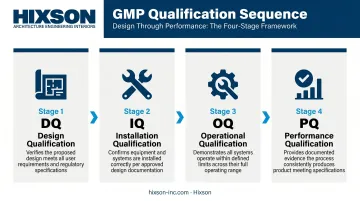
The DQ Through PQ Framework
EU GMP Annex 15 defines Design Qualification as verification that the proposed design of facilities, systems, and equipment is suitable for intended purpose. DQ begins during design — before construction starts.
The sequence:
- DQ — confirms design meets URS and GMP requirements
- IQ — verifies correct installation against engineering drawings and specifications
- OQ — tests systems across anticipated operating ranges
- PQ — confirms effective, reproducible performance under routine conditions
Design documents — P&IDs, HVAC design reports, room data sheets, equipment layouts — become the foundational evidence for IQ and OQ. Their accuracy and completeness are a compliance matter. A drawing that doesn't reflect what was built creates a gap that inspectors notice.
Change Control During Construction
Annex 15 requires that planned changes to qualified premises, facilities, utilities, or systems be formally authorized and evaluated for requalification impact. That requirement doesn't begin at startup — it applies throughout construction.
Field changes, design deviations, and material substitutions affecting GMP-critical systems must be formally documented, assessed for compliance impact, and approved before installation. As-built drawings must reflect the facility as constructed, not the facility as originally designed.
Construction administration teams that understand GMP implications of field changes provide a critical check. Hixson's CA team is specifically tasked with verifying that plans and specifications are followed on-site, with documented identification of deficiencies during regular site visits. That oversight catches a material substitution before it becomes an inspection finding.
Frequently Asked Questions
What are the core GMP principles for pharmaceutical facilities?
GMP facility principles address controlled environments, contamination prevention, layout and material flow, clean utility systems, and equipment qualification — all enforced under FDA 21 CFR Part 211, EU GMP Annex 1, and WHO guidelines during inspections.
What is the recommended layout and design for GMP pharmaceutical facilities?
GMP facility layouts follow unidirectional flow of materials and personnel, with cleanroom zoning, pressure cascades, and airlocks segregating classified spaces. Achieving this requires cross-disciplinary coordination between architecture, process engineering, and HVAC design from the earliest project phases.
What HVAC requirements apply to GMP pharmaceutical cleanrooms?
Key requirements include classification-specific air change rates, HEPA filtration, and positive pressure differential cascades between zones, with minimums of 10 Pa (EU) or 10–15 Pa (FDA) between adjacent classified areas. Sterile manufacturing areas have substantially more stringent requirements than non-sterile controlled spaces.
How does material and personnel flow affect GMP facility design?
GMP regulations require separated, unidirectional flow paths for raw materials, in-process product, personnel, and waste to prevent cross-contamination. This flow logic directly determines corridor placement, airlock design, gowning room adjacency, and door interlock configurations.
What surfaces and finishes are required in GMP pharmaceutical manufacturing areas?
GMP mandates smooth, non-porous, coved, and chemically resistant interior surfaces in classified areas, with minimized horizontal surfaces, sealed penetrations, and GMP-specific components — including sanitary pipe supports, concealed sprinkler heads, and pressure-rated doors — to support consistent and effective cleaning.
What role does qualification play in GMP facility design?
Qualification begins at the design stage with Design Qualification (DQ), which confirms the facility design meets GMP and user requirements before construction starts. Design documents then serve as foundational evidence for IQ, OQ, and PQ activities, making documentation accuracy a compliance requirement throughout the design process.