Introduction
Ice cream manufacturing puts more engineering demands on a single facility than any other food product. A single building must span an extreme thermal range: pasteurization above 80°C, aging below 5°C, and hardening tunnel temperatures as low as -40°C.
All of that happens under one roof — with raw and post-pasteurization zones physically separated and every surface cleanable to FDA standards.
A layout that looks efficient on paper can fail operationally when refrigeration piping can't reach the hardening tunnel, drain slopes conflict with equipment anchoring, or a high-care zone shares an entry point with raw material receiving. Both are structural problems that surface mid-construction or, worse, during an FDA inspection.
This guide covers the design decisions that determine whether a facility runs well from day one: zone separation and traffic flow, refrigeration and utility infrastructure, floor and drain design, and the compliance checkpoints that catch problems before construction begins.
Key Takeaways
- Lock in your product portfolio, SKU formats, and production volume targets before drawing a single zone boundary
- Follow a strict linear process flow — raw receiving through to finished goods cold storage — with no backtracking
- Plan refrigeration, CIP, drainage, and electrical distribution in parallel with the production floor plan, not after it
- Embed HACCP-based zone separation, FDA/FSMA requirements, and 3-A Sanitary Standards into the spatial layout at the start of design
- Under-planned cold storage, misplaced utility infrastructure, and siloed design disciplines are the costliest mistakes in ice cream facility projects
How to Design an Ice Cream Factory Layout
Step 1: Define Products, Volume, and Scalability Goals
Layout work can't begin meaningfully until the product portfolio is confirmed. Stick bars, cones, cups, extruded novelties, and bulk family packs each require different equipment footprints, hardening approaches, and line configurations. A facility designed for cups alone will need significant modification to accommodate a stick bar line later.
From the portfolio, establish hourly and daily volume targets per SKU category. These numbers drive equipment capacity, line count, staging area dimensions, and cold storage volume. Tetra Pak's continuous freezers range from 150–700 L/h (1.25 m² footprint) to 300–1,500 L/h (1.66 m² footprint). A cone or cup line can reach 45,000 products/hour across up to 12 lanes. Line speed determines how much floor area, refrigeration load, and dock throughput you need.
Scalability must be built in from the start. Real-world examples show what under-planning costs: Perry's Ice Cream added an 18,000 sq ft freezer to a 120,000 sq ft plant after outgrowing original capacity. Graeter's, operating a 30,000 sq ft facility producing over 6 million pints per year, later tripled frozen storage and expanded shipping and receiving docks. IDFA data confirms the busiest production months run March through September — seasonal surge alone can expose a facility sized only for average throughput.
Practical scalability measures to build in:
- Modular zone boundaries that can absorb an additional production line
- Oversized utility stub-outs at expansion areas
- Reserved floor area adjacent to existing lines
- Cold storage and dock capacity sized for peak demand, not annual average
Determine early whether the facility will run a single line or parallel lines simultaneously. A stick bar line and a cup filling line operating at the same time change how space is allocated, how utilities are distributed, and how sanitation corridors are routed.
Step 2: Map the Core Production Zones and Process Flow
The production floor must follow a strict linear sequence. Material moves one direction — from raw inputs to finished output — with no backtracking. Every loop or reversal in the flow creates cross-contamination risk, adds labor travel distance, and limits throughput.
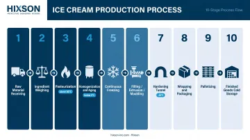
The verified process sequence for an ice cream plant:
- Raw material receiving and temperature-controlled storage
- Ingredient weighing and mix preparation
- Pasteurization (continuous, above 80°C with hold)
- Homogenization (50–200 bar) and aging (below 5°C for at least 4 hours)
- Continuous freezing
- Filling, extrusion, or moulding
- Hardening tunnel
- Wrapping and packaging
- Palletizing
- Finished goods cold storage
Hixson's process engineering team develops block flow diagrams and process flow diagrams at the front end of every project, before equipment is sized or zones are drawn. The flow sequence determines everything downstream: drain locations, refrigeration routing, CIP return lines, and zone boundaries.
Hardening Tunnel Placement
Hardening tunnel positioning is one of the most consequential spatial decisions in the layout. The tunnel must connect directly from filling/forming equipment on one end and feed into cold storage on the other. Any thermal break between these three points creates energy loss and product quality risk.
Tetra Pak data shows products spend 20–30 minutes in the hardening tunnel, with air temperatures at -40°C driving frozen water content from roughly 50% (post-continuous freezing) to at least 80%. Extrusion tunnels like the Tetra Pak M3 achieve up to 24,000 products/hour. Spiral hardening systems handle up to 2,500 kg/hour and suit space-constrained layouts where vertical accumulation is feasible. Choose the tunnel type before finalizing floor dimensions — tunnel length and footprint are non-negotiable inputs.
Zone Separation
Raw/unpasteurized areas and post-pasteurization high-care zones must be physically separated with walls, dedicated airlocks or vestibules, and separate personnel entry points. 21 CFR Part 117 allows separation by location, time, partitions, airflow, or dust control — but FDA's dairy inspection guidance is explicit: no cross-connections between raw and pasteurized product systems.
The consequences of getting this wrong are documented. FDA warning letters to Friendly's cited Listeria monocytogenes in environmental swabs matching strains from 2017 and 2019, including condensate dripping from overhead pipes directly into filler heads.
Royal Ice Cream received citations for a resident Listeria strain present since 2017, with positives on a filler head and sandwich preparation table. Both cases trace directly to layout and access failures around post-pasteurization equipment.
Step 3: Plan Supporting Infrastructure and Utilities in Parallel
Refrigeration, CIP, electrical distribution, and drainage are not supporting details to finalize after the production floor is drawn. They determine where production equipment can physically go. Treating them as a second phase is the single most expensive design mistake in ice cream facility projects.
Refrigeration
Ammonia refrigeration is common in ice cream plants, but it carries significant regulatory weight. OSHA's Process Safety Management standard applies to systems containing 10,000 lb or more of ammonia, with the same threshold triggering EPA Risk Management Program requirements.
Machine room location, ventilation design, relief routing, pipe identification, and maintenance access must all be resolved before equipment positions are locked. OSHA references ANSI/IIAR 2, 4, and 6 as the governing standards for design, installation, and ongoing inspection.
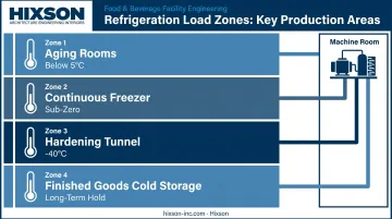
Refrigeration load spans every production zone: aging rooms (below 5°C), the continuous freezer, hardening tunnel (-40°C), and finished goods storage. The machine room location and evaporator positions directly constrain where equipment can be placed and how efficiently the cold chain is maintained across the facility.
CIP System
3-A Accepted Practice 605-05 governs installation and CIP of processing equipment and hygienic pipelines. The CIP skid should be positioned to serve the pasteurizer, aging tanks, and continuous freezer with short, drainable return runs. Dead legs, inaccessible valves, and undersized return circuits are leading contributors to cleaning failures and environmental Listeria persistence.
Drainage and Electrical
- Floor drains must be positioned and sloped before equipment is anchored — PMO requires impervious floors, proper slope, and trapped drains in all processing and storage rooms
- USDA guidelines specify minimum 4-inch floor clearance for equipment legs when base points are within 12.5 inches of an edge, and 6 inches when farther
- Electrical panel rooms should be at the production floor perimeter — accessible without personnel entering active production zones
- Group high-draw equipment (hardening tunnels, blast freezers, extruders) to reduce cable run lengths and simplify load balancing
Step 4: Design for Food Safety and Regulatory Compliance
Compliance requirements must be embedded in spatial decisions from the first layout draft. Retrofitting them after architectural drawings are complete is expensive and often requires structural changes.
Key regulatory frameworks governing the layout:
| Framework | What It Governs |
|---|---|
| 21 CFR Part 117 (FSMA) | CGMPs, facility design, space requirements, contamination prevention |
| Pasteurized Milk Ordinance (PMO) | Floors, drains, ventilation, lighting, separate rooms by function |
| 3-A Sanitary Standards | Equipment hygienic design and CIP installation |
| HACCP principles | Hazard analysis, CCPs, and physical separation of risk zones |
Specific layout requirements:
- Minimum 18–24 inches clearance between equipment and walls for cleaning access
- Equipment elevation above the floor to enable sanitation underneath
- Wall, floor, and ceiling materials rated for wet, cold environments with regular washdown
- Dedicated change rooms with boot wash and hand wash stations at high-care zone entries
- Personnel flow direction reinforces the clean-to-dirty gradient — operators should never pass through a lower-care zone to reach a higher-care area
Pest control routes, waste removal paths, and contractor access points should be designed so none cross active production areas. External utility connections minimize how often contractors need to enter food production zones.
Firms like Hixson structure their engagements so process engineers, architects, mechanical engineers, and plumbing and sanitation specialists work together throughout the layout phase — not in sequence. That coordination is what prevents compliance gaps from being discovered mid-construction when changes carry maximum cost.

Common Mistakes When Designing Ice Cream Factory Layouts
Even well-structured projects fail when these specific variables aren't controlled.
Locking Equipment Positions Before Utility Infrastructure Is Set
Facilities frequently optimize workflow positions for equipment, then discover refrigeration piping, electrical load centers, or drain slopes can't practically serve those locations without major structural changes. It's the most expensive mid-construction correction in cold food manufacturing — and one of the most preventable.
Sizing Cold Storage for Average Output, Not Peak Demand
IDFA data confirms March through September as peak production months. Sizing cold storage and outbound docks for annual-average throughput creates a capacity constraint during the months that matter most. Post-opening storage expansions at regional creameries are well-documented examples of what that decision costs operationally.
Designing Around One Product Format With No Changeover Room
A layout tuned for a single format — with no space for temporary ingredient staging, line changeover, or a second production line — becomes a bottleneck within a few years. Product mix rarely stays static after launch, and a rigid layout rarely ages well.
Frequently Asked Questions
What are the essential zones in an ice cream factory layout?
Core zones run in sequence: raw material receiving and storage, mix preparation, pasteurization, homogenization and aging, continuous freezing, filling/forming, hardening tunnel, packaging, and finished goods cold storage. Each zone must be physically bounded — through walls, airlocks, or controlled access points — to prevent cross-contamination between raw and post-pasteurization areas.
How much space does a commercial ice cream manufacturing facility typically require?
Floor area depends on production volume, number of product lines, and cold storage requirements. Published examples range from Graeter's 30,000 sq ft plant (over 6 million pints annually) to Perry's 120,000 sq ft facility to Idaho Milk Products' 183,000 sq ft new build announced in 2024. A layout study with confirmed production targets is the only reliable way to size a specific facility.
What food safety regulations govern ice cream factory layout in the United States?
The primary frameworks are FDA FSMA Preventive Controls for Human Food (21 CFR Part 117), the Pasteurized Milk Ordinance for dairy processing, 3-A Sanitary Standards for equipment and CIP design, and HACCP-based zoning principles. The physical layout must reflect these requirements — not just the documentation.
What is HACCP zoning and why does it matter for ice cream factory design?
HACCP zoning separates areas by contamination risk. For ice cream, the critical boundary runs between unpasteurized raw material areas and post-pasteurization high-care zones — a separation that must be engineered into walls, dedicated personnel flows, and air pressure differentials, not managed through procedures alone. FDA warning letters in the ice cream sector consistently cite failures at exactly this point.
How should an ice cream factory layout accommodate future capacity expansion?
Design modular zone boundaries, install oversized utility stub-outs at planned expansion areas, and reserve adjacent floor space so a parallel line or additional equipment can be added without interrupting active production. Size cold storage and docks for peak seasonal demand rather than current annual throughput.
How long does the layout design phase take for a new ice cream manufacturing facility?
Timeline depends on project complexity, site conditions, and whether the work is greenfield or brownfield — brownfield projects add existing infrastructure constraints that must be assessed and accommodated. Integrated firms running process, architectural, mechanical, and sanitation engineering in parallel can compress the schedule considerably compared to sequential engagement, where each discipline waits on the prior one.
Conclusion
A functional ice cream factory layout is the output of coordinated engineering work across multiple disciplines applied simultaneously. Get those decisions right early, and the rest of the project follows. The four fundamentals that drive every successful layout:
- Production scope and volume targets define the building grid
- A compliant linear process flow eliminates contamination risk and throughput bottlenecks
- Utilities engineered in parallel with the production layout prevent structural corrections that derail construction budgets
- Food safety requirements embedded from day one mean regulatory compliance is designed in from the start
The failures that show up in FDA warning letters, capacity constraints after two years of operation, and energy inefficiency in cold chain management almost always trace to layout decisions made early without adequate cross-discipline input.
Bringing process engineers, architects, mechanical engineers, and sanitation specialists together from the first layout draft is what keeps those problems off your plate from opening day forward.